Clip-on face plate for electrical fixtures

Inactive Publication Date: 2006-07-18
LEVITON MFG
View PDF63 Cites 16 Cited by
  • Summary
  • Abstract
  • Description
  • Claims
  • Application Information

AI Technical Summary

Benefits of technology

[0021]By applying embodiments in accordance with the present invention, a fixture may be secured to a connection box in a comparatively short amount of time. Embodiments in accordance with the present invention may be particularly advantageous when it is desirable to preserve the ability to remove the fixture from the connection box. For example, an electrician or computer network technician may need to remove a fixtur

Problems solved by technology

Manually installing screws or other fasteners is often time consuming.
Maintaining all of the components in proper alignment is often difficult and requires skill.
In any case, the complexity slows the installation process.
An electrical connection box assembly is one example of a time consuming fastener installation.
Similar problems may be encountered in the installation of connections boxes used for a wide variety of devices and systems, including without limitation telephone, stereo, computer network, information systems, cable television system, and security systems fixtures.
Often it is difficult to initiate engagement between the screw and the receiving hole.
Such difficulty typically arises because the receiving hole may be obscured by the wall paneling or recessed into the wall.
Once the screw

Method used


Image

  • Clip-on face plate for electrical fixtures
  • Clip-on face plate for electrical fixtures
  • Clip-on face plate for electrical fixtures

Examples


Example

[0063]It will be readily understood that the connection box assemblies of the present invention, as generally described and illustrated in the Figures herein, could be arranged and designed in a wide variety of different configurations. Thus, the description herein is not intended to limit the scope of the invention, but is merely representative of certain presently preferred embodiments of devices and systems in accordance with the invention. Those of ordinary skill in the art will, of course, appreciate that various modifications to the details herein may easily be made without departing from the essential characteristics of the invention, as described. Thus, the following information is intended only by way of example, and simply illustrates certain presently preferred embodiments consistent with the invention.

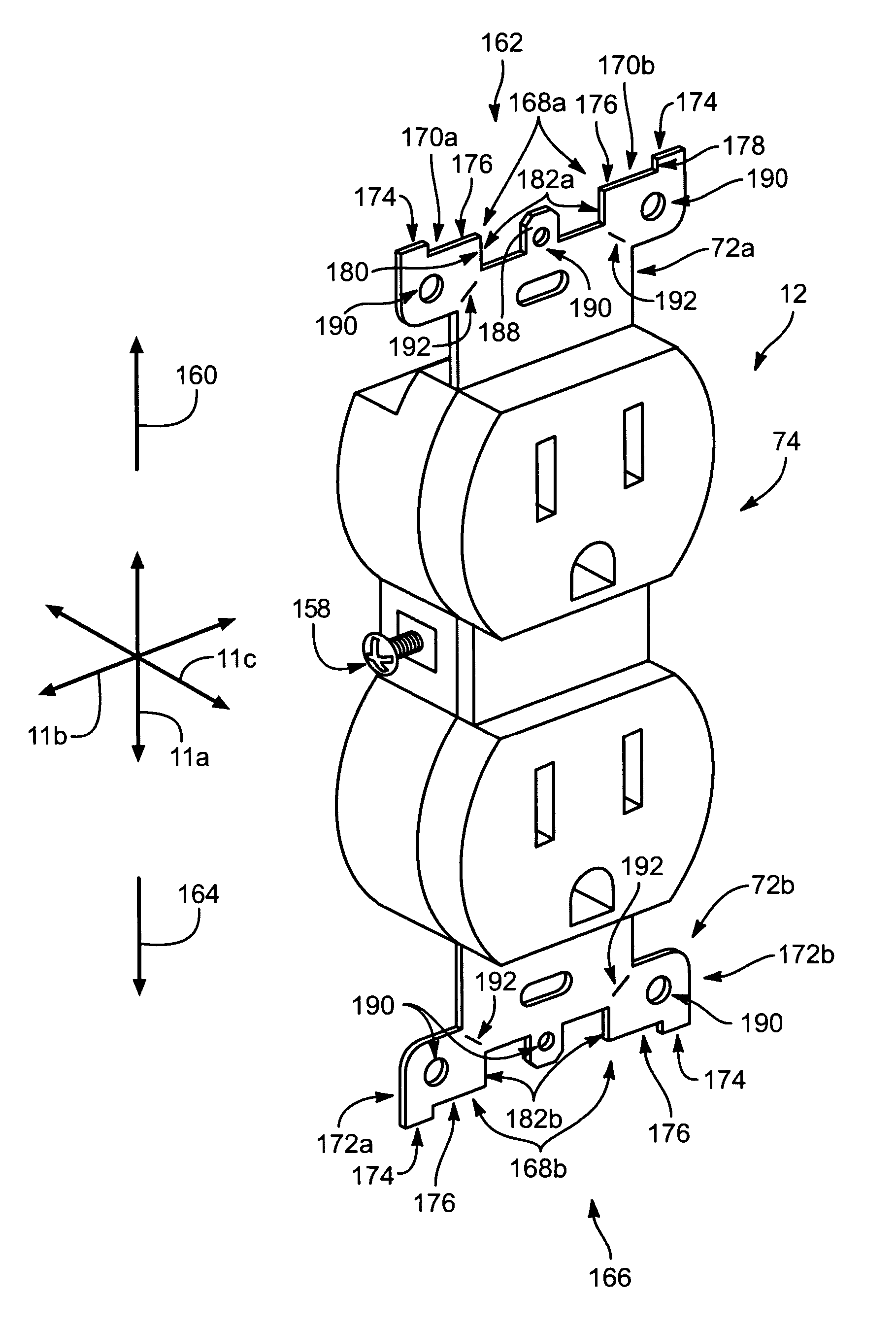
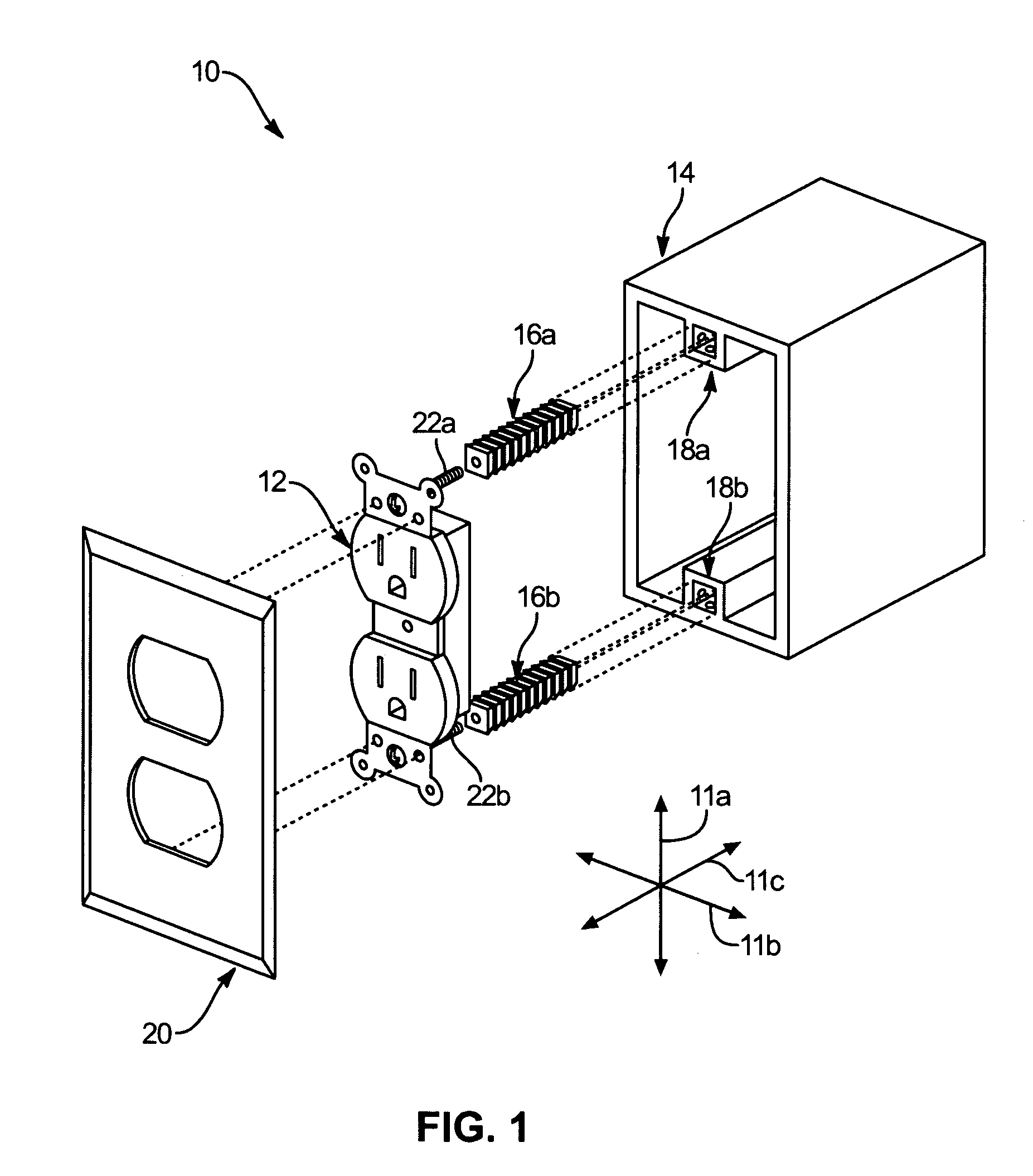
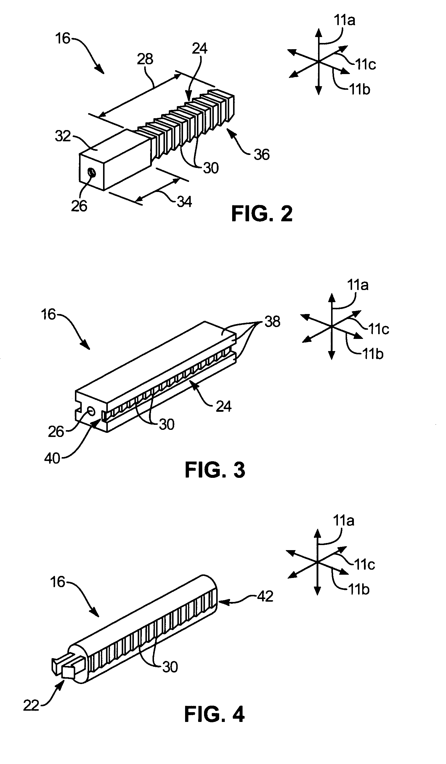
[0064]Referring to FIG. 1, in discussing the Figures, it may be advantageous to establish a reliable coordinate system to aid in the description of several of the embodimen...


PUM


Abstract

An electrical fixture comprising a body, first flange, and second flange. The body may have a terminal for securing a transmission line. The first flange may secure to the body to extend away therefrom toward a first end. The second flange may secure to the body to extend toward a second end. The first and second flanges may each include a pair of ears, the first and second pairs of ears being located proximate the first and second ends, respectively. The ears of the first and second pairs of ears may be spaced apart in a third direction substantially orthogonal to the first and second directions. The ears may be formed to have an extended portion, most distant from the body, and a recessed portion, spaced away from the extended portion toward the body and presenting an edge extending in the third direction.

Description

RELATED APPLICATIONS[0001]This application is a continuation-in-part of U.S. patent application Ser. No. 10 / 317,612 filed Dec. 12, 2002 now U.S. Pat. No. 6,679,725 and entitled CLIP-ON COVER PLATE FOR ELECTRICAL FIXTURES, which was a continuation-in-part of U.S. patent application Ser. No. 09 / 974,306 filed Oct. 10, 2001 now U.S. Pat. No. 6,609,927 and entitled QUICK ASSEMBLING ELECTRICAL CONNECTION BOX APPARATUS AND METHOD, and claimed the benefit of U.S. Provisional Application No. 60 / 343,332 filed Dec. 21, 2001, entitled CLIP-ON COVER PLATE.BACKGROUND[0002]1. The Field of the Invention[0003]This invention relates to fixture anchoring and, more particularly, to novel systems and methods for facilitating connection box assembly.[0004]2. The Background Art[0005]Manually installing screws or other fasteners is often time consuming. Additionally, in certain installations, the installer must employ his or her hands to hold several components as well as rotate a tool transferring rotatio...

Claims


Application Information

Patent Timeline
IPC IPC(8): H01R13/60H01R13/73H01R25/00H02G3/08H02G3/14H02G3/18
CPCH01R13/73H02G3/18H02G3/14H02G3/086H01R25/006
Inventor KIDMAN, BRENT L.
Owner LEVITON MFG
Why Eureka
Try Eureka