Ligament retractor assembly for use in performing knee surgery

a technology of retractors and knees, applied in the field of retractors, can solve the problems of inability to perform surgery, and high cost of instruments, and achieve the effect of reducing the risk of injury

Inactive Publication Date: 2006-07-18
GLOBAL ORTHOPAEDIC SOLUTIONS +1
View PDF17 Cites 6 Cited by
  • Summary
  • Abstract
  • Description
  • Claims
  • Application Information

AI Technical Summary

Benefits of technology

[0019]In the present invention, the lever section can be suitably inserted between a ligament and a tibial plateau. The surgical tubing can be suitably inserted into the slot so as to be fixedly retained therein. The other retractor paddle can be placed between the ligament and the opposite side of the tibial plateau. The surgical tubing can b

Problems solved by technology

One of the major problems with these prior art ligament retractors is the fact that they are formed of a rigid steel material and utilize complicated spring-type mechanisms.
As a result, the instruments are relatively expensive items.
Since they are not disposable, additional costs are associated with the maintenance of such equipment.
In other circumstances, since the instruments must be sterilized, they may, on occasion, be unavailable during surgery.
Since each of the items described in these prior art patents are relatively expensive items, it is unlikely that the hospital will keep a large supply of such retractors available.
In other circumstances, the spring-ty

Method used


Image

  • Ligament retractor assembly for use in performing knee surgery
  • Ligament retractor assembly for use in performing knee surgery
  • Ligament retractor assembly for use in performing knee surgery

Examples


Embodiment Construction

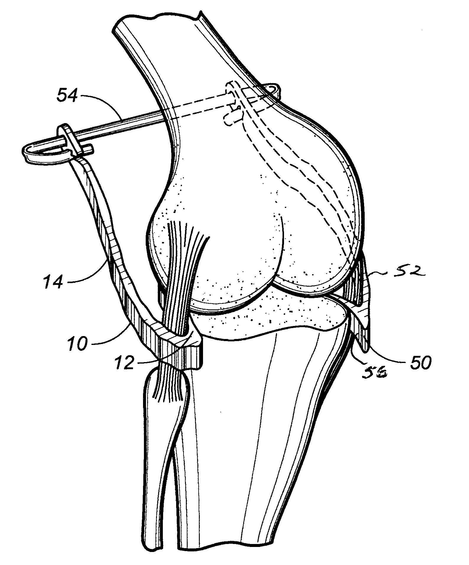
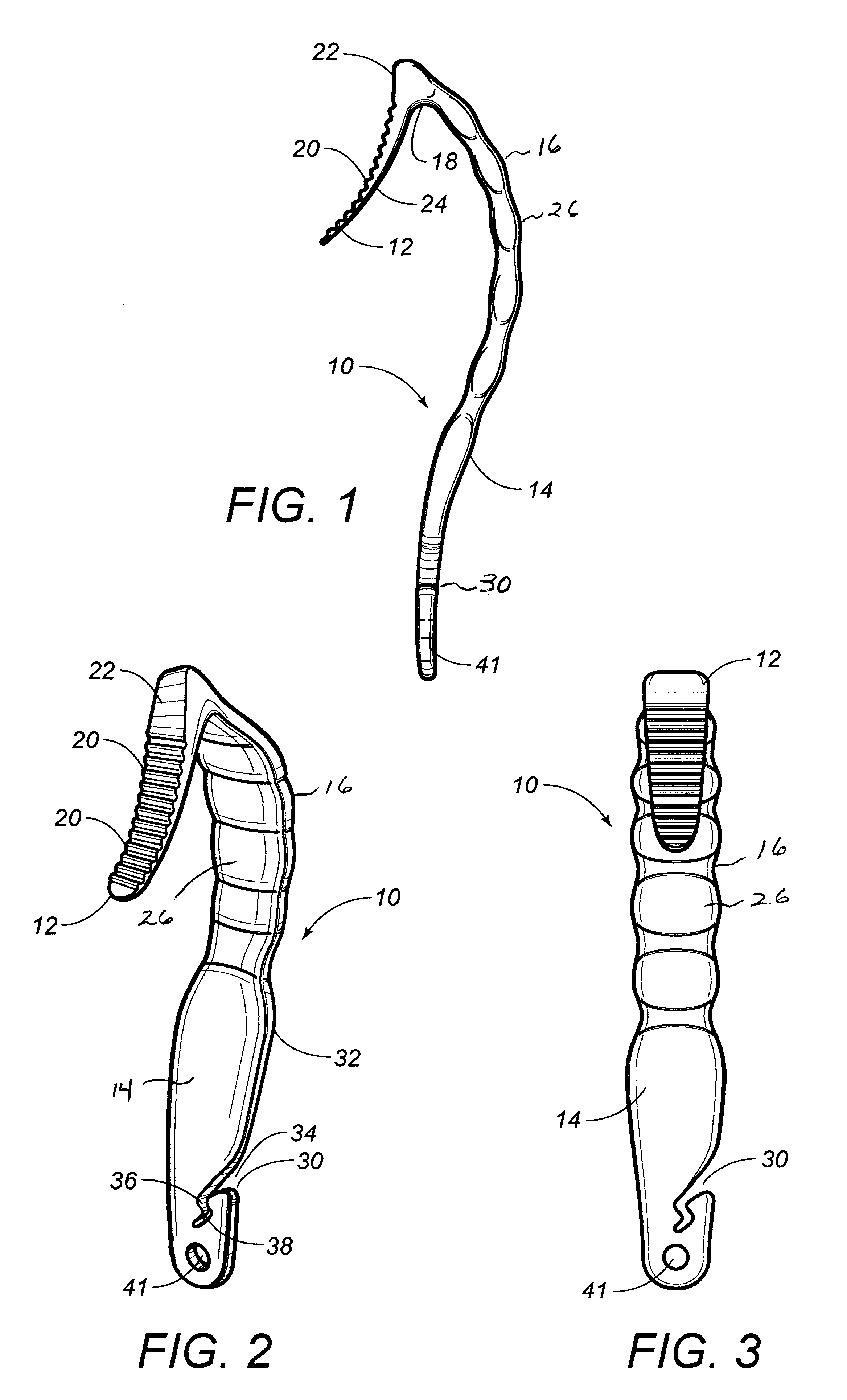
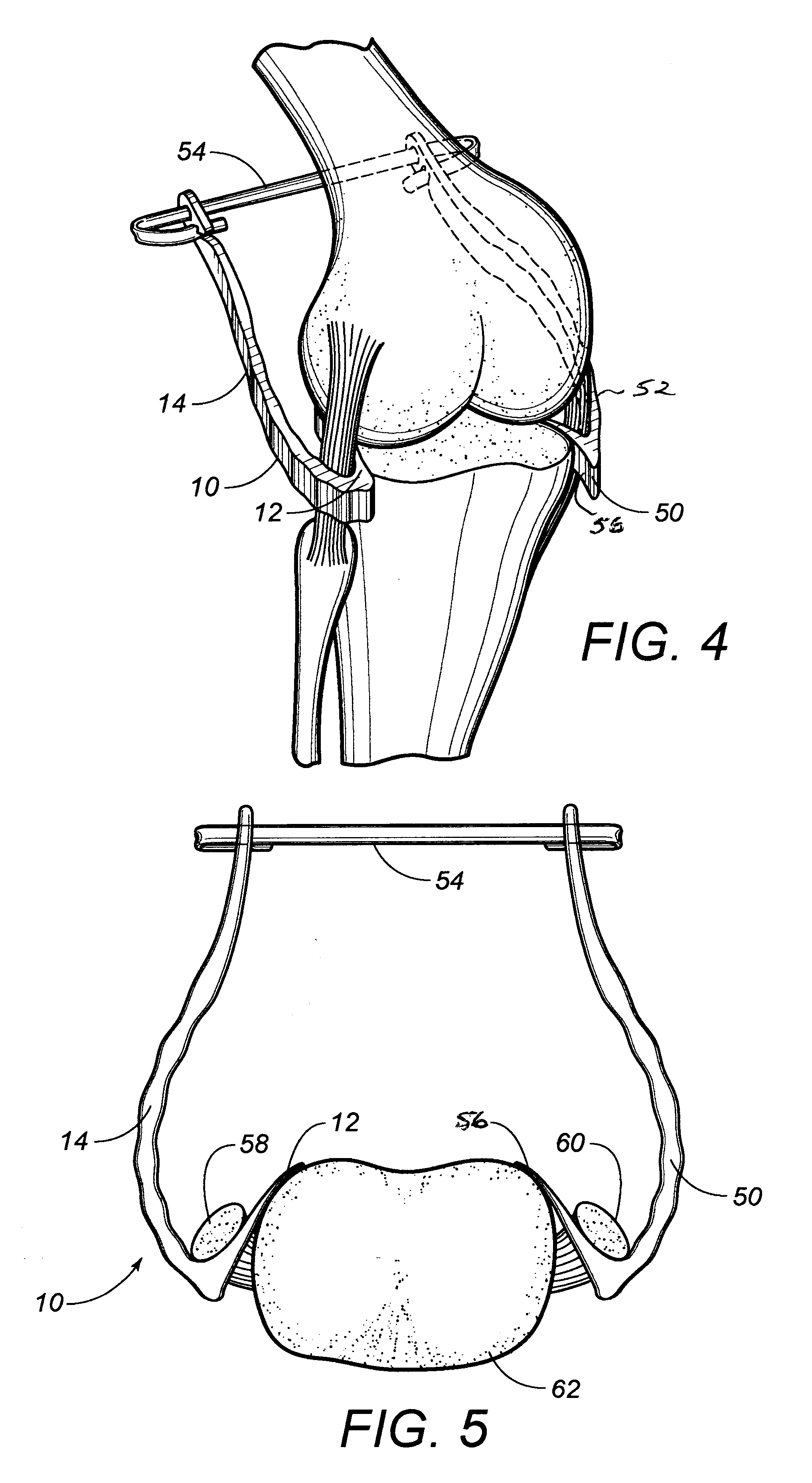
[0025]Referring to FIG. 1, there is shown at 10 the ligament retractor paddle in accordance with the teachings of the present invention. The ligament retractor paddle includes a lever section 12 and a retaining section 14. The lever section 12 and the retaining section 14 are integrally formed together of a rigid polymeric material. The lever section extends at an acute angle relative to the retaining section 14. A gripping portion 16 is formed on the surface of the retaining section 14 adjacent to lever section 12.

[0026]Since the retractor paddle 10 is formed of a polymeric material, the retractor paddle 10 can be easily disposed of subsequent to surgery. By injection molding the retractor paddle 10 in accordance with proper procedures, a large number of such retractor paddles can be formed at a relatively inexpensive cost. Suitable polymeric materials will provide the proper strength and rigidity to the structure of the retractor paddle 10 so that it is properly functional during ...


PUM


Abstract

A ligament retractor assembly including a first retractor paddle, a second retractor paddle and an elastic member having one end received in an opening of the first retractor paddle and an opposite end received by an opening of the second retractor paddle. Each of the first and second retractor paddles includes a retaining section and a lever section. The lever section extends at a generally acute angle with respect to the retaining section. The first and second retractor paddles are integrally formed of a polymeric material. Each of the first and second retractor paddles includes a gripping portion formed at an end of the retaining section adjacent the lever section. The opening is formed on the retaining section of the paddles and has a generally dog leg configuration opening at a side of the retaining section and extending at an angle toward a median of the retaining section. A hole is formed through the retaining section adjacent the opening.

Description

RELATED U.S. APPLICATIONS[0001]Not applicable.STATEMENT REGARDING FEDERALLY SPONSORED RESEARCH OR DEVELOPMENT[0002]Not applicable.REFERENCE TO MICROFICHE APPENDIX[0003]Not applicable.FIELD OF THE INVENTION[0004]The present invention relates to retractor assemblies as used during surgical procedures. More particularly, the present invention relates to ligament retractors that are used during knee surgery.BACKGROUND OF THE INVENTION[0005]In performing knee surgery, it is of the utmost importance to avoid or to at least minimize damage to ligaments, tendons, muscles, nerves and other portions of the soft tissue while gaining access to and performing surgical procedures on various portions of the bone structure of the knee. Heretofore, retractors have been utilized in performing knee surgery so as to maximize access to the bone structure intended for osteotomy procedures while, at the same time, providing maximum protection for various soft tissue members. During the knee surgery, an ap...

Claims


Application Information

Patent Timeline
IPC IPC(8): A61B1/32
CPCA61B17/025A61B2017/0268
Inventor MASSON, MARCOS V.HENRY, MARK H.
Owner GLOBAL ORTHOPAEDIC SOLUTIONS
Why Eureka
Try Eureka