Hood for a filter ventilator

a filter ventilator and hood technology, applied in the direction of cleaning dirt, crystallization separation, lighting and heating apparatus, etc., to achieve the effect of quick exchange and effortless filter exchang

Inactive Publication Date: 2006-07-18
STEGO HLDG
View PDF20 Cites 17 Cited by
  • Summary
  • Abstract
  • Description
  • Claims
  • Application Information

AI Technical Summary

Benefits of technology

[0007]It is the object of the present invention to provide a hood for a filter ventilator that has been structurally designed to enable effortless and rapid exchange of the filter.

Problems solved by technology

Advantageously, however, a pivotably mounted hood or a flap construction pivotably mounted on the hood not only provides optimal access to the filter, but at the same time allows undisturbed flow of air from the air inlet to the filter, because there has been no or only a very slight constriction of the air channel by bearings or locking devices positioned in this region.

Method used


Image

  • Hood for a filter ventilator
  • Hood for a filter ventilator
  • Hood for a filter ventilator

Examples


Embodiment Construction

[0024]In the following description, for identical parts or parts with identical actions the same reference numerals are used, although for reasons of clarity these are not all shown in each of the figures.

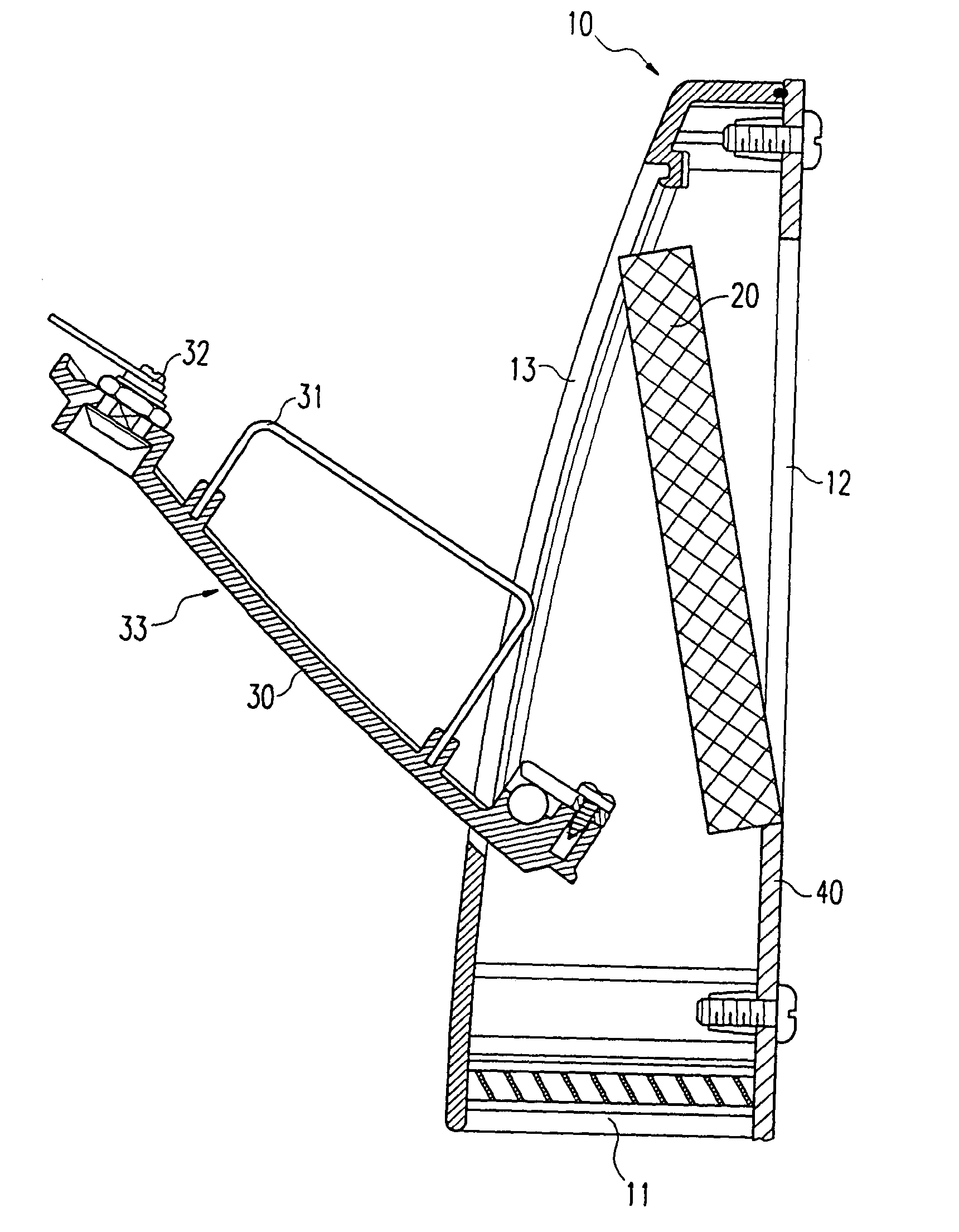
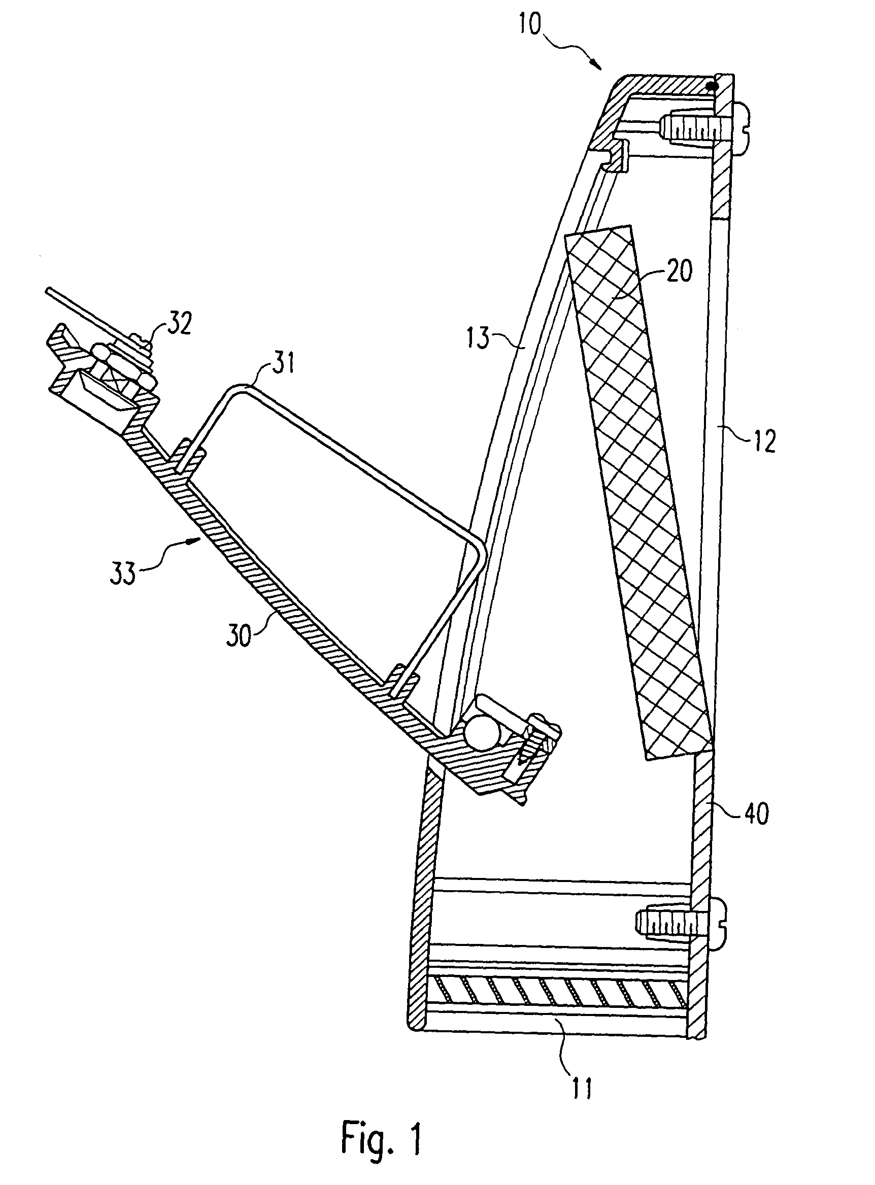
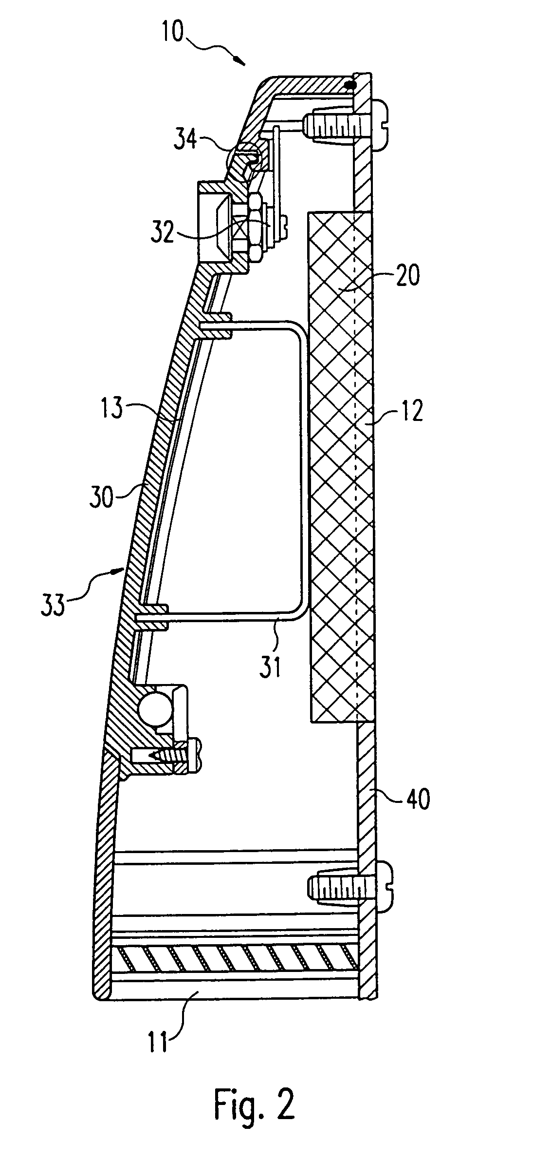
[0025]FIG. 1 is a side view in section of a hood (10) of a filter ventilator with opened flap (30), which in this position leaves the maintenance portal (13) free so that it is possible to exchange the filter (20), which here is shown partially disengaged from the air-outlet opening (12). The hood (10) itself is attached to the exterior wall (40) of a control box, circuit housing or case for various kinds of equipment, by means of screws inserted from the interior space, and comprises an air inlet (11) through which the cold air intended for cooling is sucked from outside. This entering air then flows along the internal profile of the hood (10) and finally passes through the filter (20), behind which as a rule a blower (not shown here) is disposed in the space that is to be ventila...


PUM

PropertyMeasurementUnit
flexibleaaaaaaaaaa
magneticaaaaaaaaaa
rectangular shapeaaaaaaaaaa

Abstract

The invention relates to a hood (10) for a filter ventilator, which is connected to an outside wall (40) of a space to be ventilated, in particular the outside wall (40) of a control box, circuit housing, or case for various kinds of devices, and which includes an air inlet (11), an air outlet (12), a filter (20) mounted in the air outlet and a maintenance portal (13), in particular for exchanging the filter (20). In order to enable effortless and rapid exchange of the filter, the maintenance portal (13) is made such that it can be closed by at least one pivotable flap 30.

Description

RELATED U.S. APPLICATIONS[0001]This application is a continuation of corresponding PCT application No. PCT / EP01 / 11727 filed Oct. 10, 2001 and designating the U.S.STATEMENT REGARDING FEDERALLY SPONSORED RESEARCH OR DEVELOPMENT[0002]Not applicable.REFERENCE TO MICROFICHE APPENDIX[0003]Not applicable.FIELD OF THE INVENTION[0004]The invention relates to a hood for a filter ventilator.BACKGROUND OF THE INVENTION[0005]Filter ventilators of the kind concerned here are known in the state of the art and are used primarily for ventilating the interiors of control boxes, circuit housings, and cases enclosing various other kinds of apparatus. In order to dissipate the heat generated by electronic control devices and other circuitry, a filter ventilator is used to introduce cold fresh air; this air is propelled through a hood mounted on a wall that separates the space to be ventilated from the exterior, is then passed through a filter positioned in an opening in this wall, and is finally expelle...

Claims


Application Information

Patent Timeline
Patent Type & Authority Patents(United States)
IPC IPC(8): B01D35/30B01D46/00F24F7/06B01D46/10B01D46/42F24F13/28H05K7/20
CPCB01D46/0004B01D46/008H05K7/20181F24F13/28B01D46/10B01D2265/024B01D46/88
Inventor GUILLIARD, DIETMAR
Owner STEGO HLDG
Why Eureka
Try Eureka