Electrical connector and assembly of the electrical connector and a circuit board

a technology of electrical connectors and circuit boards, which is applied in the direction of fixed connections, printed circuit aspects, printed circuit manufacturing, etc., can solve the problems of insufficient liquid tin for soldering each conductive terminal in short circuit, and insufficient tin for each solder hole, so as to prevent the occurrence of short circuit and increase the liquid tin for each conductive terminal on the respective solder hole

Inactive Publication Date: 2015-02-12
LITE ON ELECTRONICS (GUANGZHOU) LTD +1
View PDF7 Cites 14 Cited by
  • Summary
  • Abstract
  • Description
  • Claims
  • Application Information

AI Technical Summary

Benefits of technology

[0019]The efficiency of this invention resides in that the amount of liquid tin for soldering each conductive terminal on the respective solder hole can be effectively increased, and direct connection of the resilient arms of each two adjacent ones of the conductive terminals after the liquid tin is solidified can be effectively prevented to thereby prevent the occurrence of short circuit. Further, the liquid tin is prevented from directly contacting the bottom surface of the insulating body when it flows out of the top end of each solder hole, thereby preventing the insulating body from being in contact with and being damaged by the high-temperature liquid tin.

Problems solved by technology

1. Because a top end of each solder hole is closed by the insulating body, the top end of each solder hole cannot communicate with the ambient atmosphere. When the liquid tin flows into each solder hole through a bottom end thereof, the liquid tin cannot completely fill up each solder hole, so that the amount of liquid tin for soldering each conductive terminal in the respective solder hole may be insufficient.
2. Because each conductive terminal that protrudes from a bottom surface of the circuit board is long, each two adjacent ones of the conductive terminals are likely to be connected to each other after the liquid tin is solidified, thereby possibly causing a short circuit.
3. Because the bottom surface of the insulating body is in contact with the high-temperature liquid tin for a long time, the insulating body is likely to melt and get damaged.
4. Based on the aforesaid phenomenon, the assembly and the soldering quality of the board in connector and the circuit board are easily affected, even causing waste of maintenance time during machine production and increase in losses and costs.

Method used


Image

  • Electrical connector and assembly of the electrical connector and a circuit board
  • Electrical connector and assembly of the electrical connector and a circuit board
  • Electrical connector and assembly of the electrical connector and a circuit board

Examples


Embodiment Construction

[0027]Before the present invention is described in greater detail, it should be noted herein that like elements are denoted by the same reference numerals throughout the disclosure.

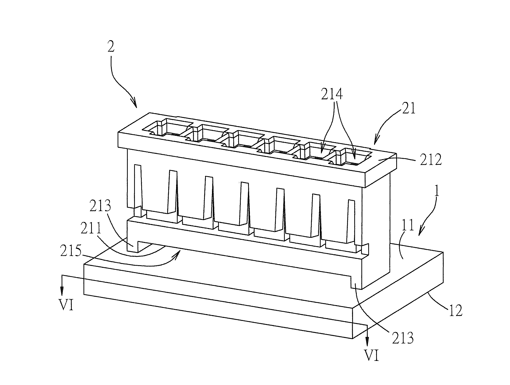
[0028]FIG. 1 illustrates the preferred embodiment of an assembly of an electrical connector and a circuit board according to the present invention. The assembly is suitable for use in a power supply, and comprises a circuit board 1, and an electrical connector 2 mounted on the circuit board 1.

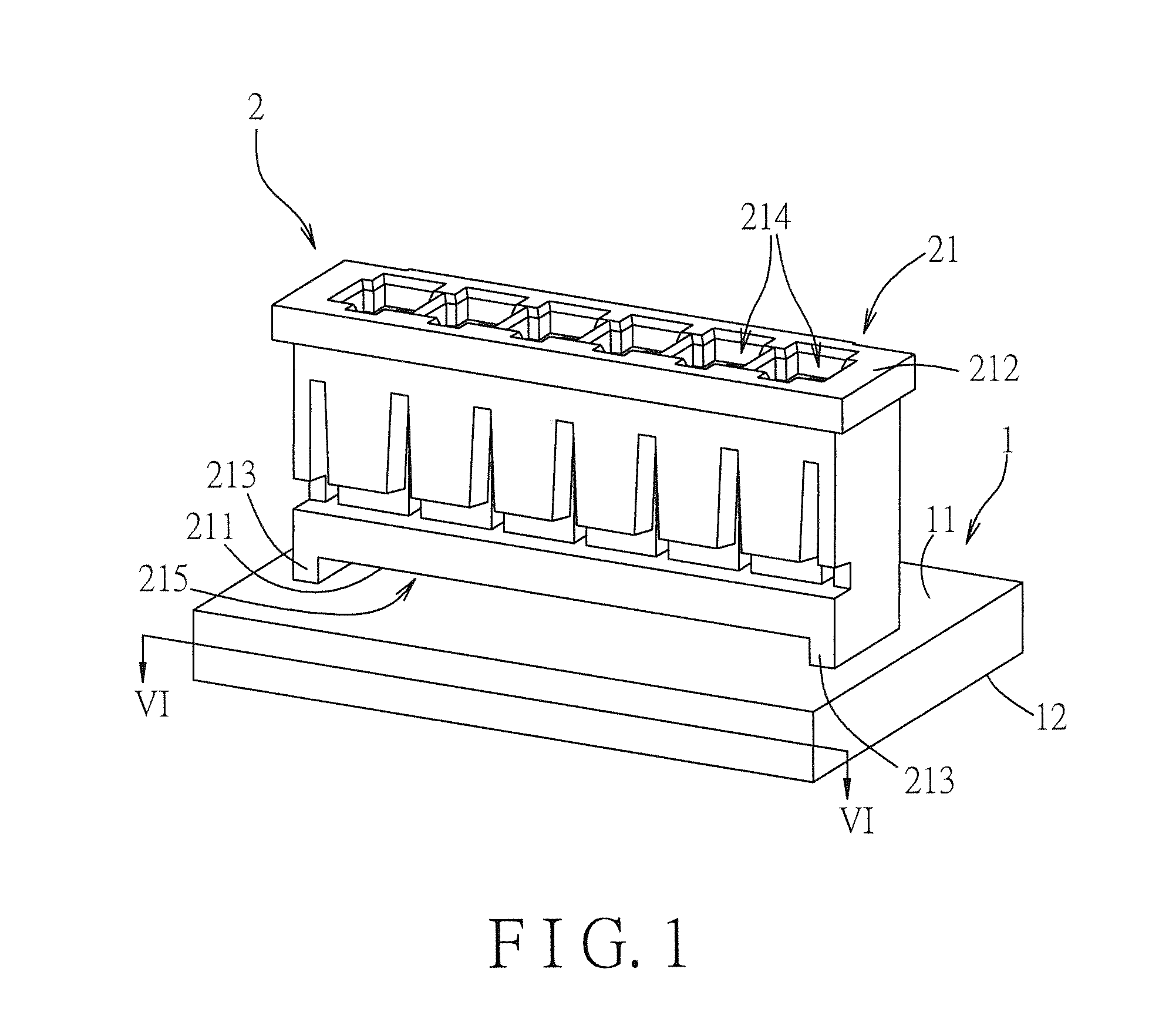
[0029]Referring to FIGS. 2 to 4, the circuit board 1 includes a top surface 11, a bottom surface 12, and at least one solder hole 13 extending through the top and bottom surfaces 11, 12. In this embodiment, a plurality of the solder holes 13 are exemplified. The electrical connector 2 is a board in connector, and includes an insulating body 1 and at least one conductive terminal 22. In this embodiment, a plurality of the conductive terminals 22 are exemplified. The insulating body 21 includes a bottom surface 211, a ...


PUM


Abstract

An electrical connector includes an insulating body having a bottom surface, a receiving groove formed in the bottom surface, and at least one support block projecting downwardly from the bottom surface for connection with a circuit board and cooperating with the bottom surface to define a venting space that communicates with the receiving groove and a solder hole in the circuit board. A conductive terminal includes a first positioning portion extending into and positioned in the receiving groove, and a second positioning portion connected to the first positioning portion and extending through the venting space and adapted to be positioned in the solder hole.

Description

CROSS REFERENCE TO RELATED APPLICATION[0001]This application claims priority of Chinese Patent Application No. 201320486960.4, filed on Aug. 9, 2013, the disclosure of which is incorporated herein by reference.BACKGROUND OF THE INVENTION[0002]1. Field of the Invention[0003]This invention relates to an electrical connector, more particularly to an electrical connector that is in contact with a circuit board through a support block and an assembly of the electrical connector and the circuit board.[0004]2. Description of the Related Art[0005]A conventional board in connector comprises an insulating body, and a plurality of conductive terminals disposed on the insulating body. To solder and fix the board in connector to the circuit board, the conductive terminals of the board in connector are first inserted into a plurality of solder holes of the circuit board, respectively, such that a bottom surface of the insulating body abuts flatly against a top surface of the circuit board. An ass...

Claims


Application Information

Patent Timeline
Patent Type & Authority Applications(United States)
IPC IPC(8): H01R4/02H05K1/11H01R12/57
CPCH01R4/02H05K1/11H01R12/57H01R12/585H01R12/707H01R12/716H05K3/3447H05K2201/10189H05K2201/10856H05K2201/10878
Inventor WANG, CHUNG-FUYAO, NIEN-HUNGYANG, HSIN-YUKAO, YU-SHAN
Owner LITE ON ELECTRONICS (GUANGZHOU) LTD
Why Eureka
Try Eureka