
Modular plasma ARC waste vitrification system

a technology of waste vitrification system and plasma arc, which is applied in the direction of incinerator apparatus, combustion types, lighting and heating apparatus, etc., can solve the problems of limiting the usefulness of hazardous waste landfills, increasing the availability of landfills, and imposing additional disposal costs, so as to reduce the deterioration of structural components.

Inactive Publication Date: 2006-12-07
LIU SAMUEL Y
View PDF4 Cites 13 Cited by
  • Summary
  • Abstract
  • Description
  • Claims
  • Application Information

AI Technical Summary

Benefits of technology

[0008] In view of the shortcomings of the prior plasma arc systems, it is a principal object of the present invention to provide an improved plasma arc system in which the crucible is designed to minimize deterioration of its structural components and refractory lining due to its operation.
[0009] It is another object of the invention to provide an improved plasma arc system in which the crucible is designed to maintain and extend the expected service life for the DC-arc electrodes and the AC joule-heating electrodes.
[0010] It is yet another object of the invention to provide an improved plasma arc system in which the crucible is designed to facilitate disassembly and reassembly for convenient repair or maintenance.

Problems solved by technology

However, a major byproduct of incinerators is waste ash that has to be transported and buried in landfills as hazardous waste.
Landfills permitted for hazardous waste are becoming increasingly unavailable and impose an added cost for disposal.
The byproducts of incinerators have also raised heightened public concern over gaseous emissions, requiring remediation with costly air pollution control systems, and the possibility of leaching from waste ash disposed in landfills and contamination of groundwater.
However, the prior plasma arc systems have had several major disadvantages which limit their usefulness.
The large plenum space has required the arc electrodes to be of long length to extend from their ceiling mounting to the plasma zone above the glass melt, making them more vulnerable to deterioration, and requiring frequent maintenance.
Due to the difficulty of maintaining the plasma zone at the desired high ionization temperatures of 10,000 to 12,000° C. with each feed cycle, a longer time was required for the waste material to stay in the plasma zone for complete decomposition.
Excess carbon collecting in the plasma field from organic constituents of waste can cause electrical “crazing” or “incandescence” which results in a loss of arc conduction and reduced effectiveness of the plasma arc ionization of waste.
The prior plasma arc systems also had design flaws which limited their useful life and required frequent and extensive maintenance.
The relatively long time it took to process a given quantity of waste material would result in the melt pool becoming stratified as between metal constituents and non-metal constituents (slag), which has led to problems with metal deposits clogging and damaging the refractory lining of the bottom floor of the crucible, and requiring frequent repair or maintenance.
The crucible design with a large plenum space above the melt pool and arc electrodes and waste input and gas output ports mounted through the ceiling wall made the ceiling half of the crucible very heavy and difficult to disassemble and reassemble for repair or maintenance.
The crucible's large size, e.g., 10-12 feet in height, and heavy weight, e.g., 40,000 lbs., made construction of a plasma arc facility a complex construction task requiring fixed siting and making it difficult to install, disassemble, and move such facilities into / from populated areas as well as remote areas which may need its special type of waste processing capability, such as in medical crisis zones, military deployments, and war zones.

Method used


Image

  • Modular plasma ARC waste vitrification system
  • Modular plasma ARC waste vitrification system
  • Modular plasma ARC waste vitrification system

Examples


Embodiment Construction

[0026] As a background for description of the invention system, reference is made to a prior art type of plasma arc vitrification system as described in U.S. Pat. No. 5,811,752 issued Dec. 8, 1998 to Titus et al, and to an integrated solid waste processing system preferred for processing biomedical or hazardous waste as described in U.S. Pat. No. 6,766,751 issued Jul. 27, 2004, to the same inventor as this U.S. patent application, which are incorporated by reference herein.

[0027] The general principles of operation of a prior art plasma arc vitrification system will now be briefly described with reference to FIG. 6. A prior art plasma arc vitrification system 10 includes a reaction vessel 12 having top 12a, bottom 12b, and sides 12c and 12d. Bottom 12b may have a generally V-shaped configuration. Reaction vessel 12 further includes at least one port or opening 14a through its top by which waste material 40 is introduced into reaction vessel 12. The reaction vessel 12 includes a plu...


PUM


Abstract

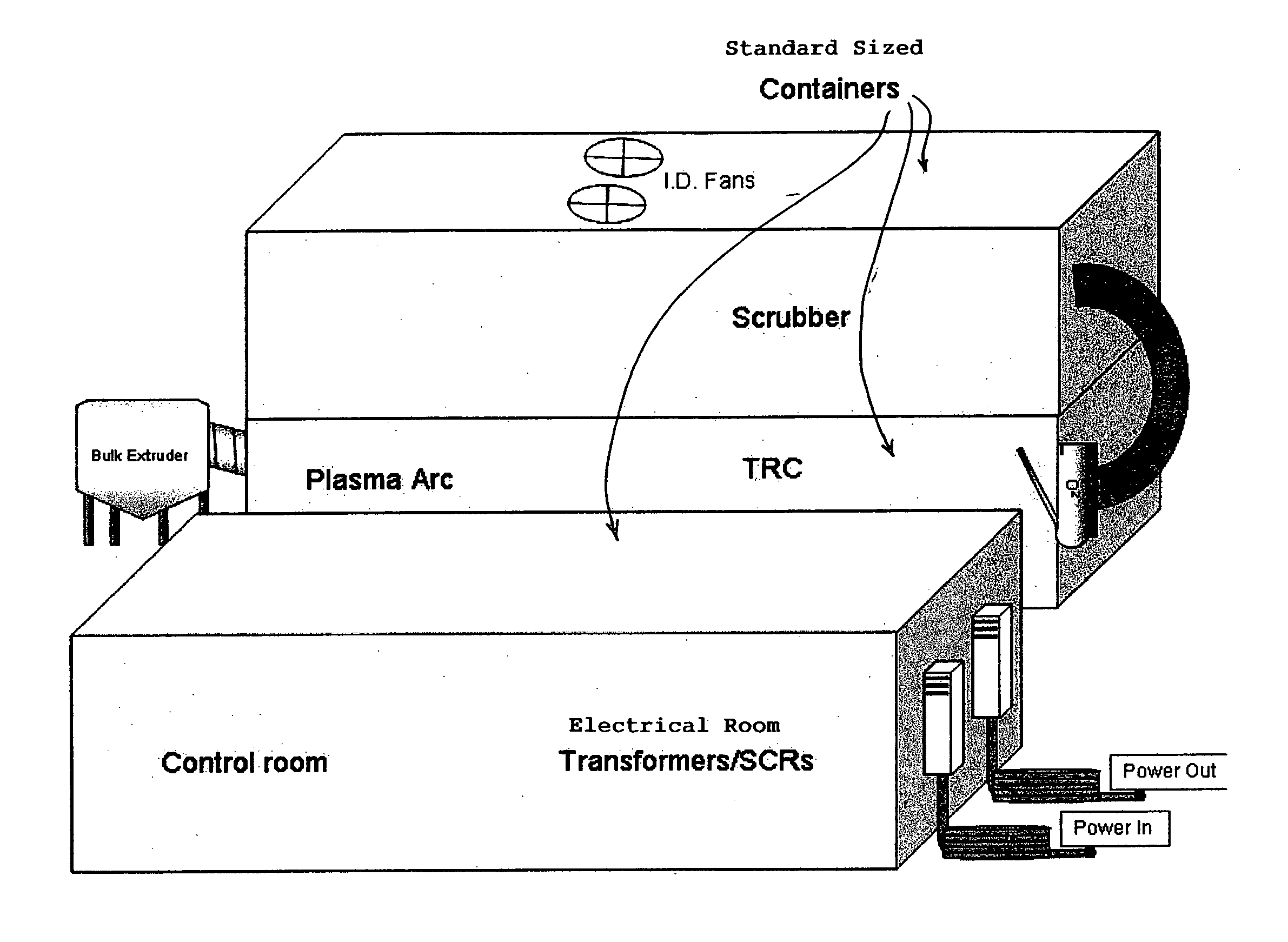
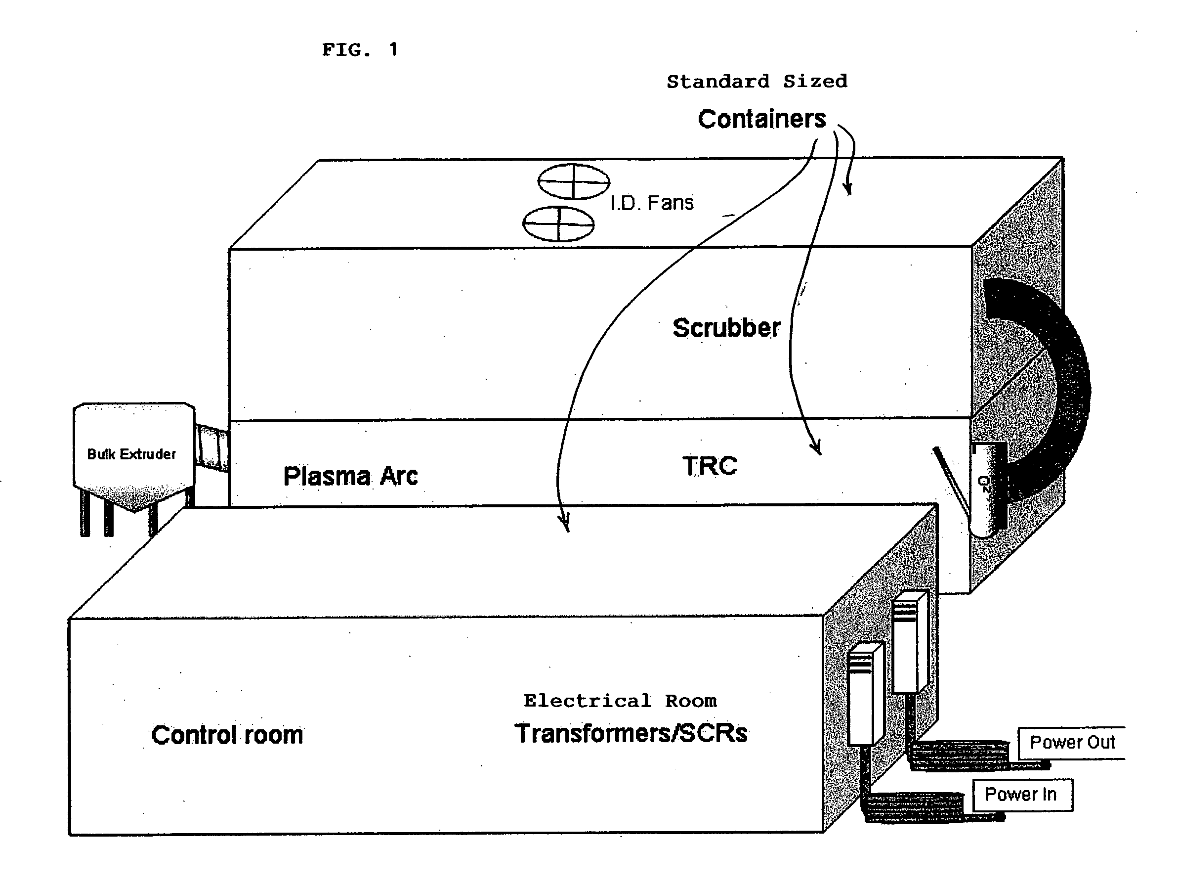
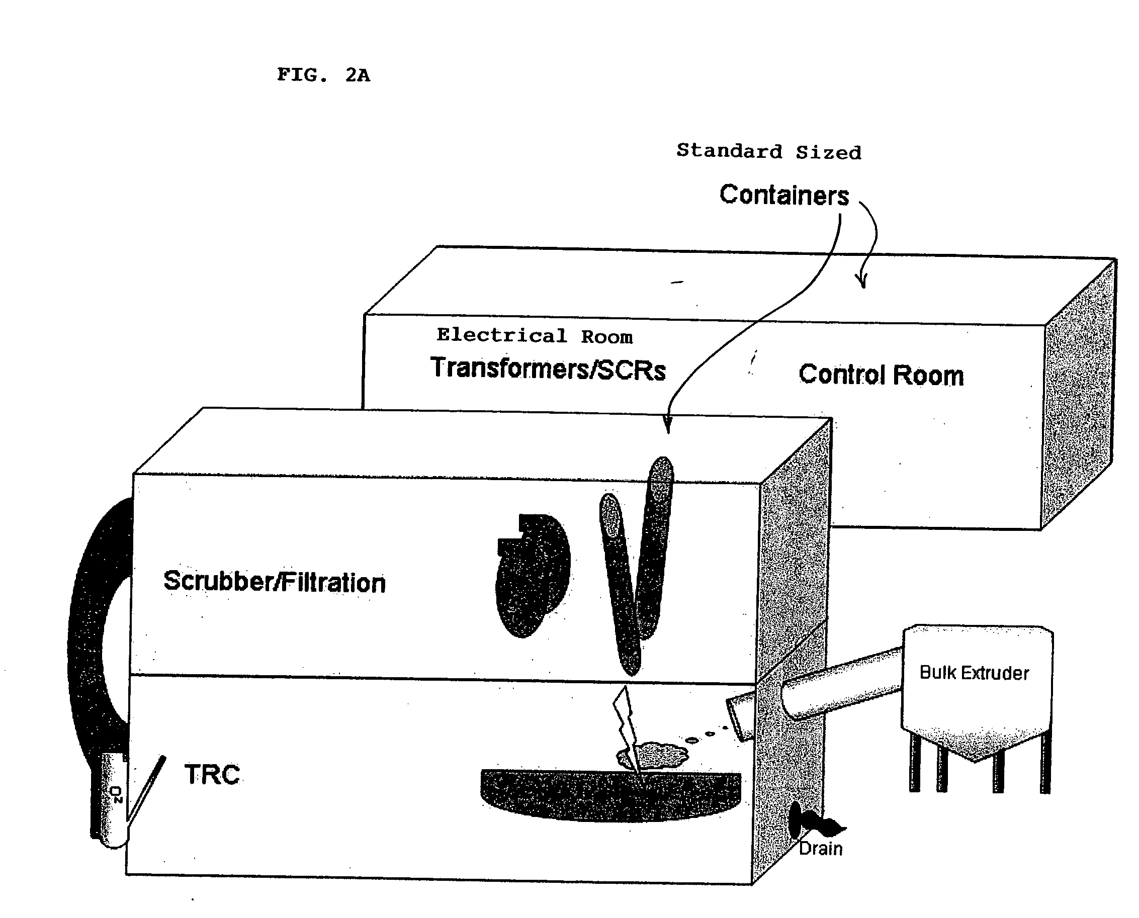
An improved plasma arc waste processing system has a crucible formed in a horizontally elongated shape with a low-ceiling-height plenum space above a melt pool and a waste input feed arranged sideways into the crucible. The plenum space conducts the off-gases through a channel into a horizontally adjacent, thermal resonant chamber. The combined volume of the plenum space and thermal resonant chamber provides a high ratio of plenum volume to surface area of melt pool for efficient pyrolization of waste at high throughput rates. The crucible and other system components can be arranged in standard sized cargo containers, to be modularly transported and assembled in populated areas or transported to and from remote areas, such as in medical crisis zones, military deployments, and war zones. As a further improvement, a water injector is used to inject water into the plasma field to remove excess carbon and form useful gas byrpoducts.

Description

TECHNICAL FIELD [0001] The present invention generally relates to plasma arc waste vitrification systems, and more particularly, to a system designed to be modular in construction so as to be readily deployed on location and to be highly efficient in waste processing. BACKGROUND OF THE INVENTION [0002] With environmental concerns imposing increasing constraints on the dumping raw solid waste into landfills or ocean beds, incinerator facilities have been utilized in recent decades to reduce the volume of waste that has to go into landfills, and to convert at least a portion of the waste stream to usable byproducts, fuels, or recoverable energy. However, a major byproduct of incinerators is waste ash that has to be transported and buried in landfills as hazardous waste. Landfills permitted for hazardous waste are becoming increasingly unavailable and impose an added cost for disposal. The byproducts of incinerators have also raised heightened public concern over gaseous emissions, req...

Claims


Application Information

Patent Timeline
IPC IPC(8): F23G5/10F23G7/00
CPCF23G5/085F23G5/10F23G5/16Y02E20/12F23G2202/20F23L2900/07008F23G5/40
Inventor LIU, SAMUEL Y.
Owner LIU SAMUEL Y
Learn More