Electric power tool

a technology of electric power tools and electric motors, applied in the direction of portable power tools, magnetic circuit rotating parts, magnetic circuit shapes/forms/construction, etc., can solve the problems of electric power tool breakdown, foregoing self-cooling motors still have problems, cutting powder becomes powder dust and floats therearound, etc., to improve heat dissipation efficiency, efficient cooling of heated parts, and long durability

Inactive Publication Date: 2008-06-26
JEFCOM
View PDF33 Cites 14 Cited by
  • Summary
  • Abstract
  • Description
  • Claims
  • Application Information

AI Technical Summary

Benefits of technology

[0016]Being constructed as stated above, the electric power tool according to the present invention includes a rotor which enables to sufficiently cool not only the body part but als

Problems solved by technology

However, depending on the workpieces to be cut or drilled, while they are being cut or drilled, some kinds of cutting powders become powder dust and float therearound.
As a result, the powder dust is contained in the outside air introduced into the tool body and adheres to the rotor and other parts to cause the breakdown of the electric power tool.
However, the foregoing self-cooling motor s

Method used


Image

  • Electric power tool
  • Electric power tool
  • Electric power tool

Examples


Embodiment Construction

[0032]Preferable embodiments of an electric power tool according to the present invention will be described below in detail with reference to the drawings.

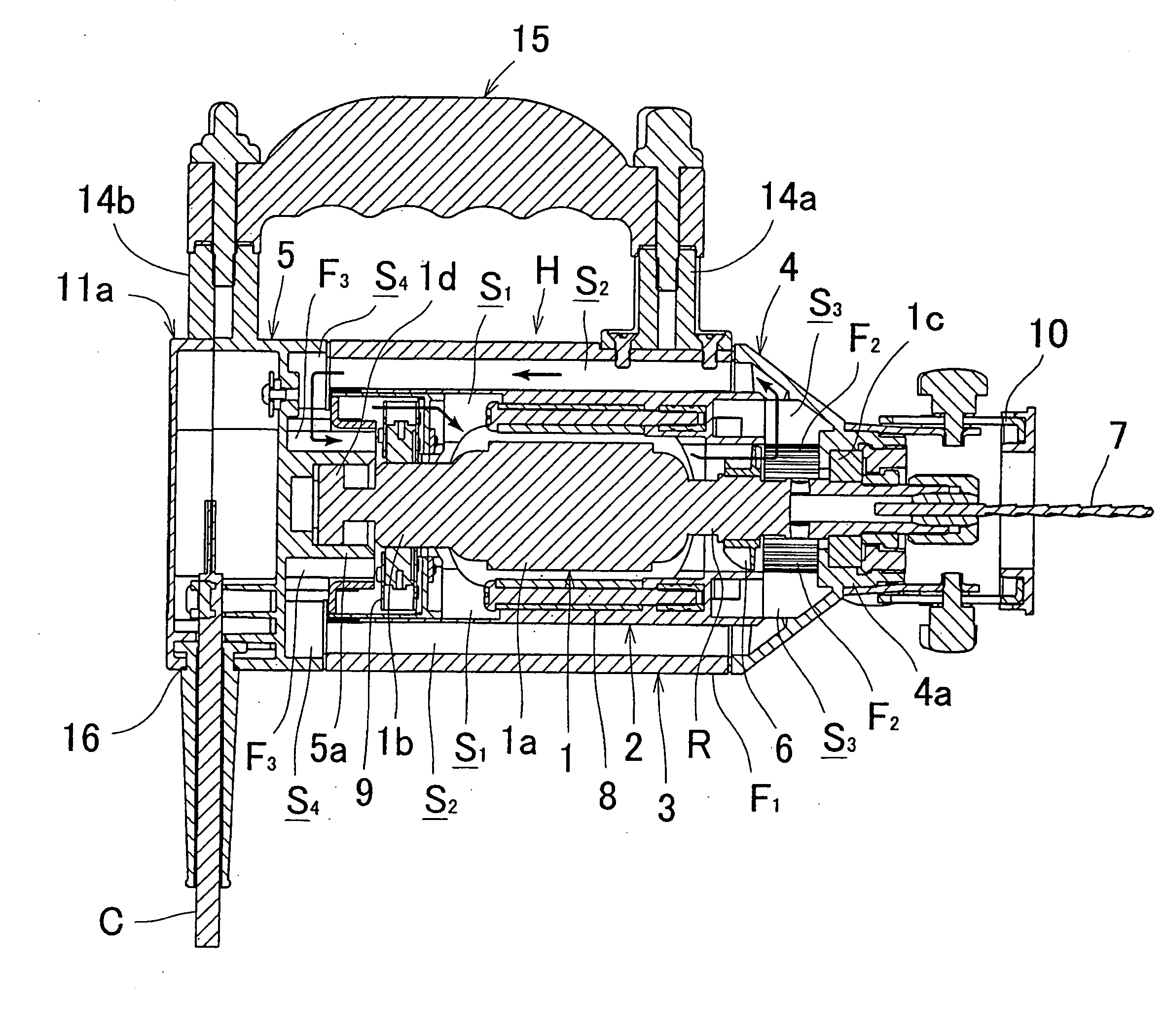
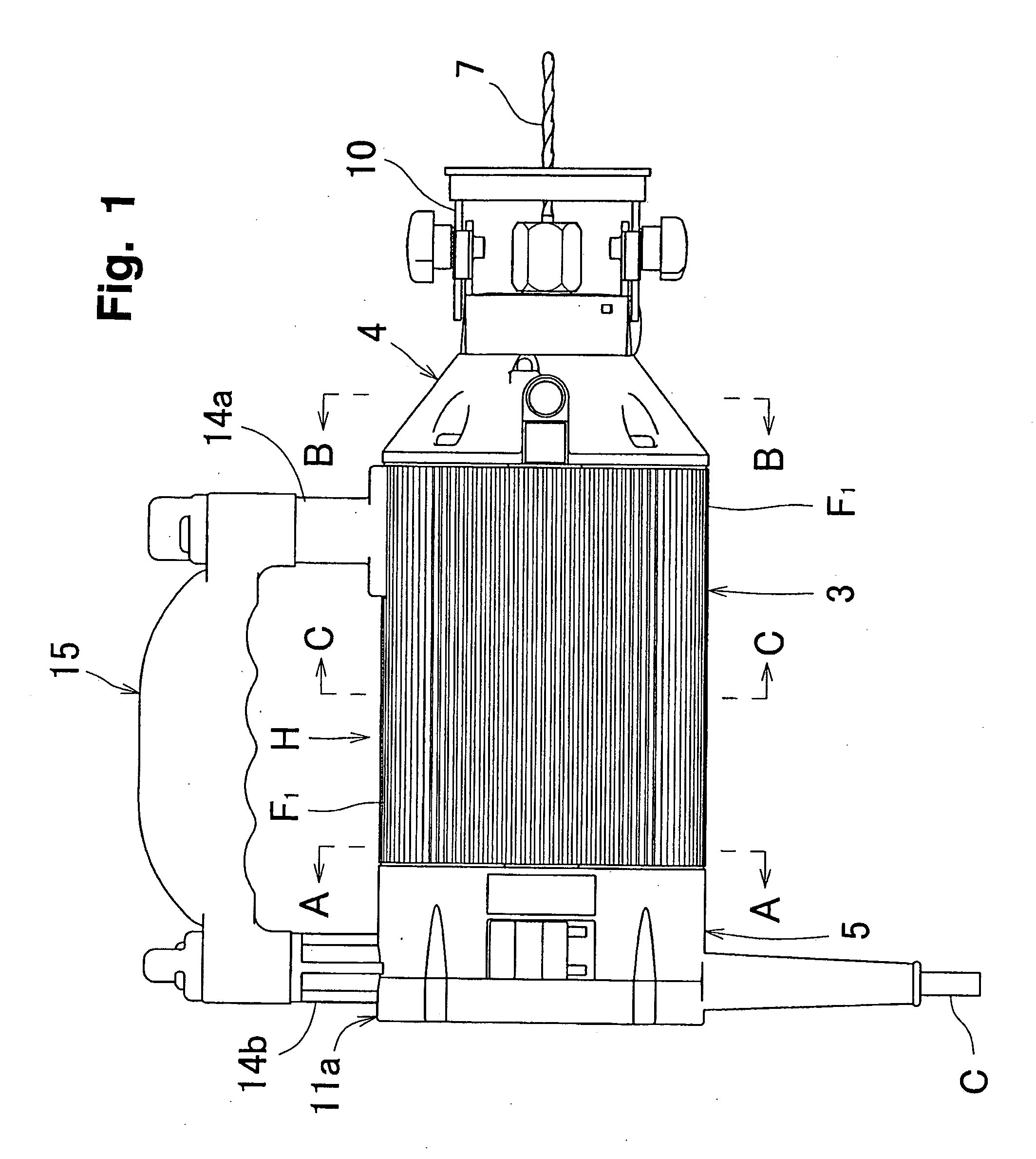
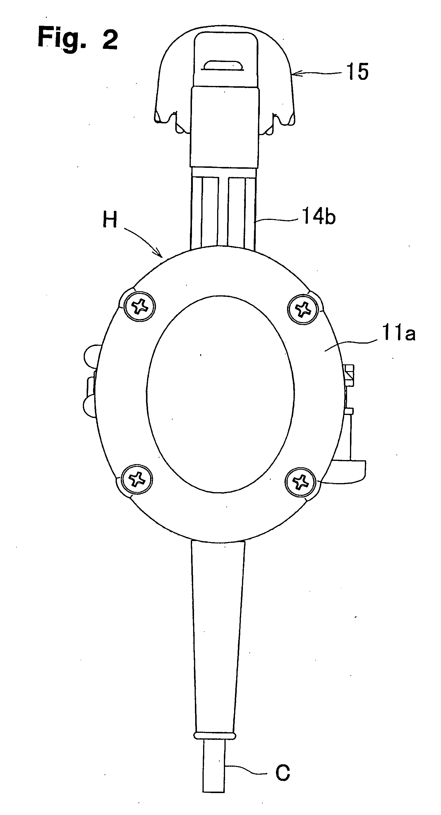
[0033]Embodiments are shown in FIGS. 1 to 3 or FIGS. 4 to 6. An electric power tool according to the present invention includes a tool body H having a rotor 1, an inner cylindrical body 2 and an outer cylindrical body 3. The inner cylindrical body 2 houses the rotor 1 with a ventilation space S1 therearound, and is inserted into the outer cylindrical body 3 which has a plurality of groove-shaped ventilation spaces S2 on its upper and lower parts of the inner face and a plurality of heat dissipation fins F1 on its outer circumferential face. The outer cylindrical body 3 has, on its front end, a ventilation space S3 covered with a front cap 4, and, on its rear end, a ventilation space S4 covered with a rear cap 5. In the electric power tool according to the present invention, the rotation of a fan 6 which is attached to the rotor 1 ...


PUM


Abstract

An electric power tool includes a tool body having a rotor, an inner cylindrical body and outer cylindrical body. The rotor is provided with a ventilation space therearound, a body part and a brush contact part, and housed in the inner cylindrical body. The inner cylindrical body is inserted in the outer cylindrical body which has a plurality of groove-like ventilation spaces on its inner face. The rotation of a fan fitted on the rotor circulates air within the tool body through the ventilation spaces so as to cool down the body part and the brush contact part of the rotor. The electric power tool has the rotor with which not only the body part but also other heated parts are fully cooled down. The electric power tool enhances heat dissipation efficiency from a motor case, enables efficient cooling of heated parts and has a long durability.

Description

BACKGROUND OF THE INVENTION[0001]1. Field of the Invention[0002]The present invention relates to an electric power tool used for cutting and drilling in electric works, building works or the like.[0003]2. Description of the Related Art[0004]Heated parts in an electric power tool of this kind, such as a support bearing, a rotor body, and a brush contact part of a rotor, has been conventionally cooled in such a manner that outside air is introduced from a rear part of the tool by a fan provided within the tool body, applied to the heated part to absorb the heat thereof, and discharged from a front part of the tool. However, depending on the workpieces to be cut or drilled, while they are being cut or drilled, some kinds of cutting powders become powder dust and float therearound. As a result, the powder dust is contained in the outside air introduced into the tool body and adheres to the rotor and other parts to cause the breakdown of the electric power tool.[0005]Thus, a self-cooling...

Claims


Application Information

Patent Timeline
IPC IPC(8): H02K9/06H02K7/14
CPCB25F5/008H02K9/10H02K5/20H02K5/18H02K5/207
Inventor SHIMA, KENSUKE
Owner JEFCOM
Why Eureka
Try Eureka