Paint Drying System

a technology for drying systems and paints, applied in drying machines, drying, light and heating equipment, etc., can solve the problems of increasing the drying time of water-borne paints using conventional systems, increasing the drying time of water-borne paints, and water entering the finished surfa

Inactive Publication Date: 2013-03-28
LESICKA MARK BRIAN
View PDF8 Cites 13 Cited by
  • Summary
  • Abstract
  • Description
  • Claims
  • Application Information

AI Technical Summary

Problems solved by technology

Furthermore, application of waterborne paints using conventional systems has significantly increased drying time in many cases.
However, in many instances, using a conventional paint drying spray-booth has resulted in increased time for drying water-borne paints.
This is due to conventional systems relying on the volatility of the paint solvent to dry the paint quickly.
Others have attempted to apply air directly onto the freshly painted surface of the automobile and have found that water becomes entrained in the finished surface and paint blistering occurred.
Furthermore, industrial shops that use various coating

Method used


Image

  • Paint Drying System
  • Paint Drying System
  • Paint Drying System

Examples


Embodiment Construction

[0020]The present invention is best understood by reference to the detailed figures and description set forth herein.

[0021]Embodiments of the invention are discussed below with reference to the Figures. However, those skilled in the art will readily appreciate that the detailed description given herein with respect to these figures is for explanatory purposes as the invention extends beyond these limited embodiments. For example, it should be appreciated that those skilled in the art will, in light of the teachings of the present invention, recognize a multiplicity of alternate and suitable approaches, depending upon the needs of the particular application, to implement the functionality of any given detail described herein, beyond the particular implementation choices in the following embodiments described and shown. That is, there are numerous modifications and variations of the invention that are too numerous to be listed but that all fit within the scope of the invention. Also, ...


PUM


Abstract

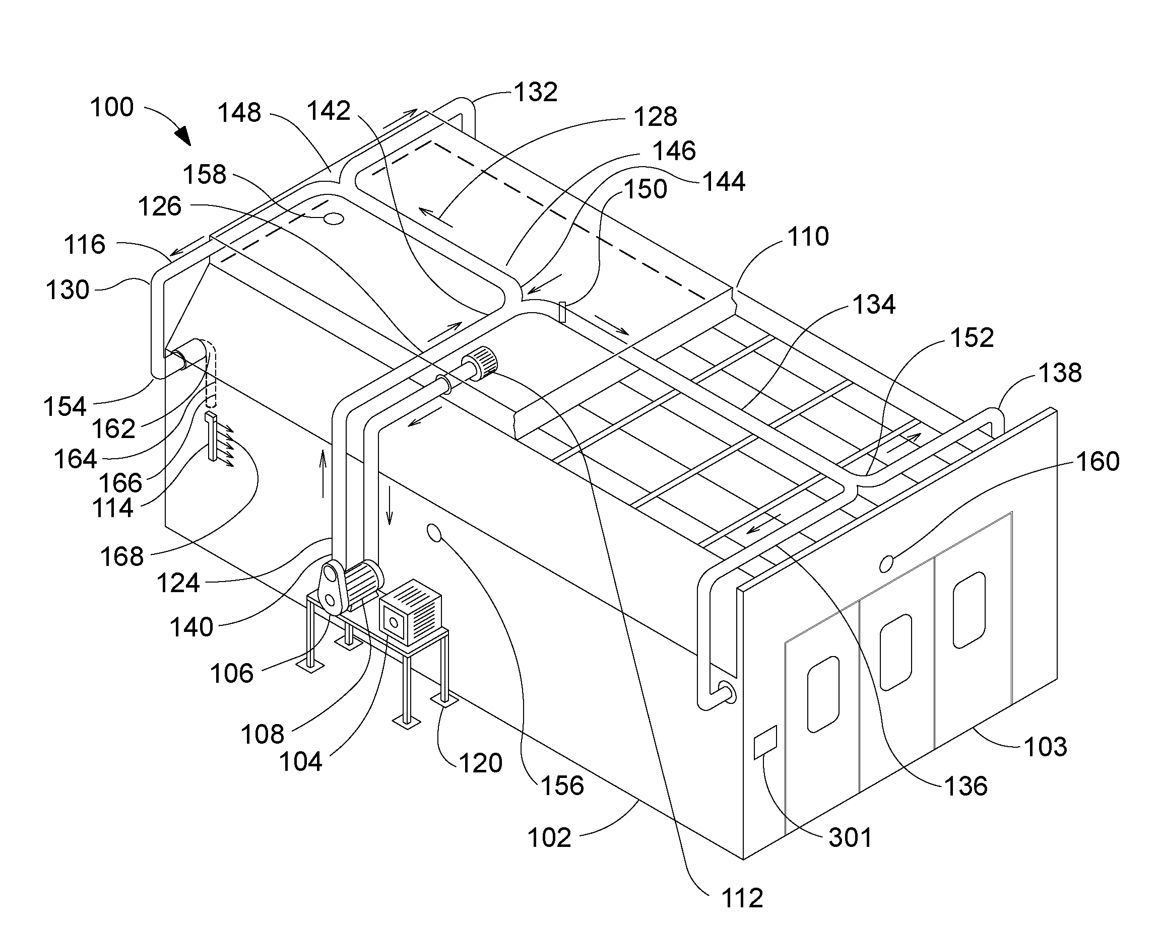
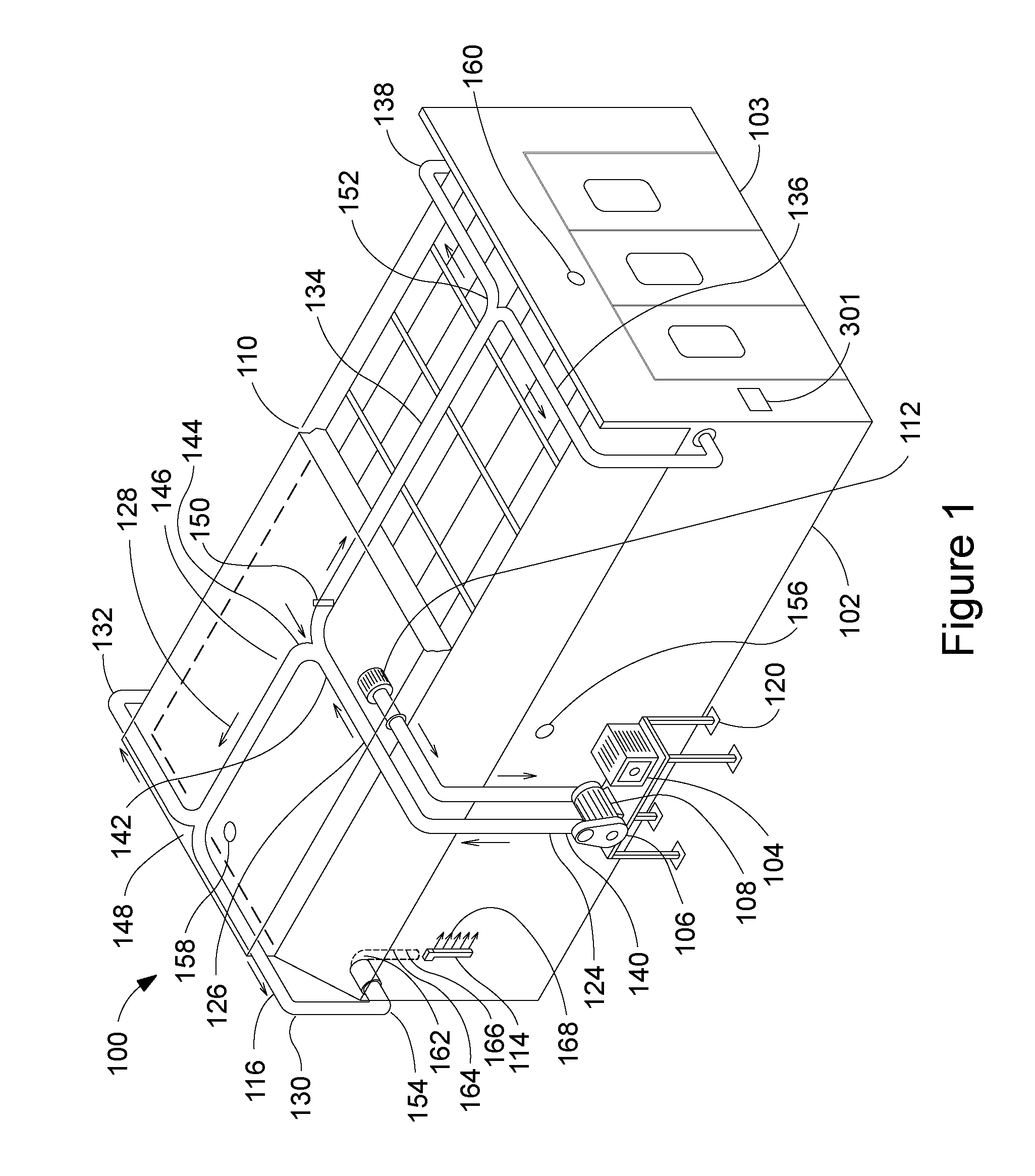
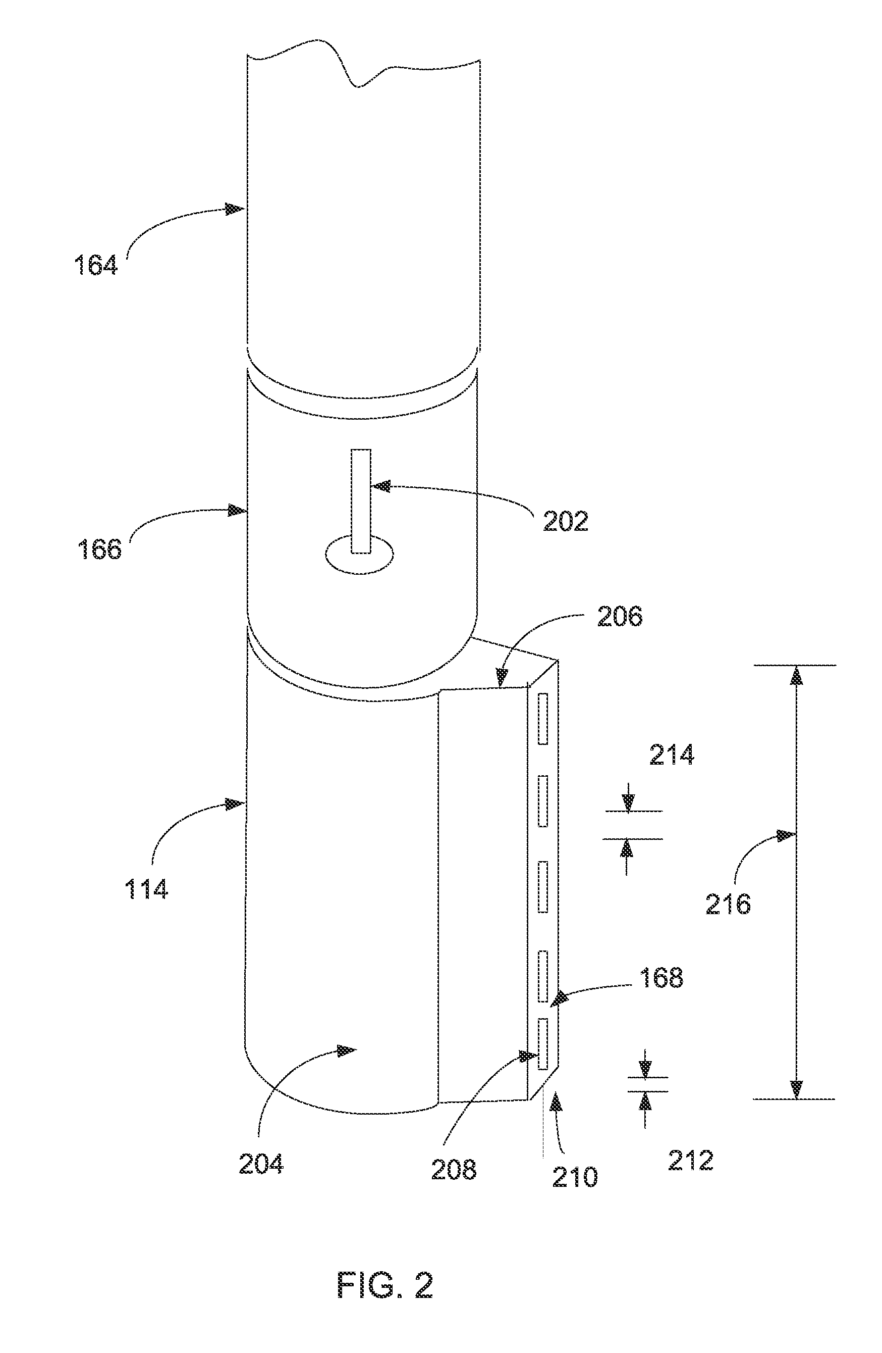
A system comprises a blower for moving a volume of air. A motor is operable for controlling the blower. A cooling unit is operable for cooling bearings of the blower during operation. An intake conduit is configured for passing heated air from a plenum space atop of a paint spray booth enclosure to the blower. A delivery conduit delivers the heated air to a plurality of locations within the paint spray booth enclosure. A plurality of air knifes are joined to the delivery conduit at the plurality of locations to deliver a laminar flow of the heated air into the paint spray booth. A plurality of comb devices, each joined to a one of the plurality of air knifes, are configured to disrupt the laminar flow to produce a turbulent flow in which an object within the paint spray booth enclosure is surrounded by the turbulent flow of heated air.

Description

FEDERALLY SPONSORED RESEARCH OR DEVELOPMENT[0001]Not applicable.REFERENCE TO SEQUENCE LISTING, A TABLE, OR A COMPUTER LISTING APPENDIX[0002]Not applicable.COPYRIGHT NOTICE[0003]A portion of the disclosure of this patent document contains material that is subject to copyright protection. The copyright owner has no objection to the facsimile reproduction by anyone of the patent document or patent disclosure as it appears in the Patent and Trademark Office, patent file or records, but otherwise reserves all copyright rights whatsoever.FIELD OF THE INVENTION[0004]One or more embodiments of the invention generally relate to a paint drying system. More particularly, the invention relates to a system for drying painted motor vehicles.BACKGROUND OF THE INVENTION[0005]Recently released regulations implemented by the Environment Protection Agency (EPA) have begun eliminating solvent based paints in many areas of the U.S. and have started mandating waterborne paints. The use of waterborne pain...

Claims


Application Information

Patent Timeline
IPC IPC(8): F26B21/00
CPCF26B21/12F26B21/004
Inventor LESICKA, MARK BRIAN
Owner LESICKA MARK BRIAN
Why Eureka
Try Eureka