Method for Removing Deposit from Substrate and Method for Drying Substrate, as Well as Apparatus for Removing Deposit from Substrate and Apparatus for Drying Substrate Using These Methods

a technology for removing deposits and substrates, which is applied in the direction of cleaning using liquids, drying machines with progressive movements, furnaces, etc., can solve the problems of difficult to sufficiently dry substrates and inability to easily remove, and achieve the effect of reducing the size of particles, ensuring stability, and accelerating the size of deposits

Inactive Publication Date: 2007-12-06
MITSUBOSHI DIAMOND IND CO LTD
View PDF3 Cites 26 Cited by
  • Summary
  • Abstract
  • Description
  • Claims
  • Application Information

AI Technical Summary

Benefits of technology

[0030] In the method for removing deposit from a substrate according to Claim 1 of the invention, a fluid on a substrate is compressed in a fluid introduction path, and then, the fluid spreads in the fluid lead-out path, and therefore, the deposit on the main surface of the substrate is converted to microscopic particles without aggregating and can be easily removed from the main surface of the substrate.
[0031] In accordance with the invention according to Claim 2, the Venturi effect between an air knife unit and the main surface of the substrate is used when a fluid passes through the fluid lead-out path, and the air knife unit is supported relative to the main surface of the substrate in such a manner as to fluctuate, so that the clearance between the air knife unit and the main surface of the substrate is adjusted, and therefore, effects can be gained, such that the air knife unit follows bending and inclination of the substrate in a simple mechanism, so that the above described clearance can be stably maintained.
[0032] In accordance with the invention according to Claim 3, air knife units are paired in the configuration, and in each pair, a fluid that is discharged from the slit portion of one air knife unit has the appearance of a wall surface and a fluid that is discharged from the slit portion of the other air knife is made to collide with the above described wall surface, and fur

Problems solved by technology

The liquid that has attached to end surface portion C cannot easily be r

Method used


Image

  • Method for Removing Deposit from Substrate and Method for Drying Substrate, as Well as Apparatus for Removing Deposit from Substrate and Apparatus for Drying Substrate Using These Methods
  • Method for Removing Deposit from Substrate and Method for Drying Substrate, as Well as Apparatus for Removing Deposit from Substrate and Apparatus for Drying Substrate Using These Methods
  • Method for Removing Deposit from Substrate and Method for Drying Substrate, as Well as Apparatus for Removing Deposit from Substrate and Apparatus for Drying Substrate Using These Methods

Examples


first embodiment

[0085] In this first embodiment, an apparatus for drying a substrate is described as an apparatus for removing deposit from a substrate.

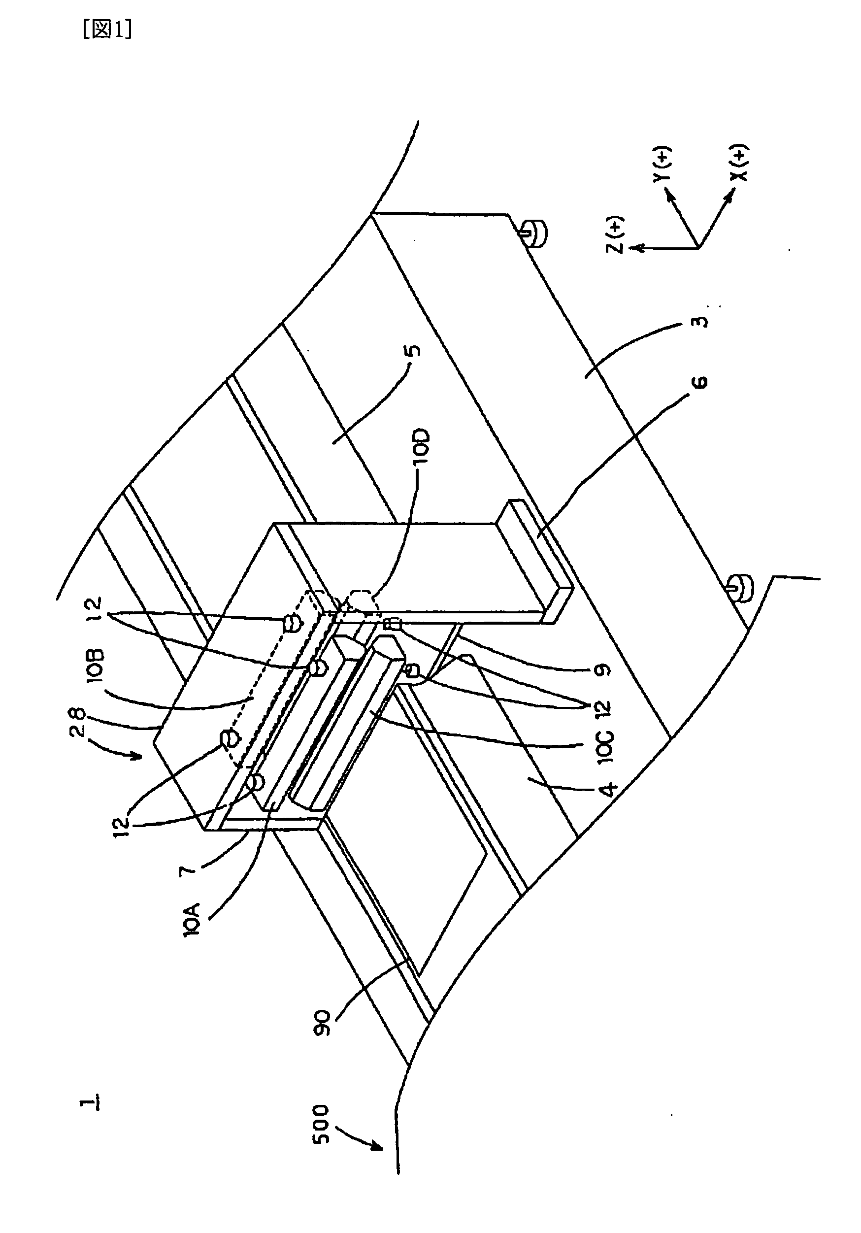
[0086]FIG. 1 is a schematic perspective diagram showing an example of an apparatus for drying a substrate of the present invention. This apparatus for drying a substrate a substrate 90 by removing a liquid that has attached to the front and rear surface of substrate 90 in a step after an apparatus for processing a substrate 500 has processed rate 90.

[0087] Apparatus for processing a substrate 500 in the previous step is, for example, an apparatus for cleaning a substrate, an apparatus for polishing a substrate, a dicing apparatus, an apparatus for etching a substrate or the like. Here, in some cases, an apparatus for drying a substrate 1 of the present invention may be provided within apparatus for processing a substrate 500 in the previous step.

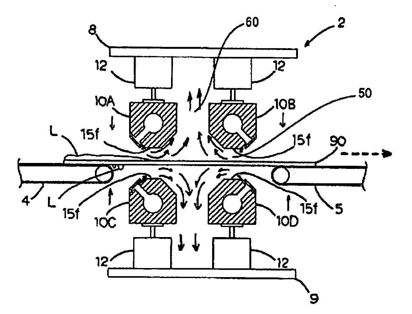
[0088] An apparatus for drying a substrate 1 is formed of a portion for processing a substrate 2 which...

second embodiment

[0121] Another mode of the means for adjusting the clearance is shown in the second embodiment.

[0122]FIG. 6 is a schematic perspective diagram showing an apparatus for drying a substrate according to the second embodiment of the present invention.

[0123] The apparatus for drying a substrate 100 of FIG. 6 is not structurally different from apparatus for drying a substrate 1 in the first embodiment, but unit holding portion 12 of portion for processing a substrate 2 is replaced with another unit holding portion 30, and therefore, description of the respective members is omitted, and the same symbols as those in the first embodiment are used for corresponding members.

[0124]FIG. 7 is a schematic cross sectional 1 diagram showing the configuration of unit holding portion 30.

[0125] Unit holding portion 30 is described in reference to FIG. 7.

[0126] A casing 32 is a member in cylindrical form where a flange 32a is formed in such a manner as to be integrated with the lower portion, and h...

third embodiment

[0131] Another mode of the air knife unit is shown in the third embodiment.

[0132] The third embodiment is different form the first and second embodiments in that a pair of air knife units are coupled and integrated, and a number of holes for releasing a fluid are formed in the integrated unit.

[0133]FIG. 8 is a cross sectional diagram showing portion for processing a substrate 2 of apparatus for drying a substrate 150 according to the third embodiment of the present invention.

[0134]FIG. 9 is a perspective diagram showing the appearance of coupled air knife unit 160 which is provided in portion for processing a substrate 2 of apparatus for drying a substrate 150 according to the third embodiment of the present invention.

[0135] As shown in FIGS. 8 and 9, this coupled air knife unit 160 is held by the pair of unit holding portions 12 and 12 of the first embodiment or the pair of unit holding portions 30 and 30 of the second embodiment, and the unit holding portions are linked to upp...


PUM


Abstract

In a method for removing deposit that has attached to a main surface of a substrate from the main surface of the substrate using air knife units where a slit portion is formed so that a fluid can be discharged in band form, a fluid introduction path having an approximately uniform form in the direction perpendicular to the direction in which a number of air knife units move relative to the substrate is formed between the air knife units and the main surface of the substrate while the air knife units move relative to the substrate, a fluid is discharged toward the fluid introduction path from a slit that is formed in the rear portion of the above described air knife units, and then, passes through the fluid introduction path so as to be led to a wall surface that is formed so as to face the front portion of the air knife units or the fluid which has the appearance of a wall surface, and furthermore, deposit on the substrate that has attached to the substrate is led away from the main surface of the substrate, together with said fluid, via a fluid lead-out path of which the cross sectional area of the low path is greater than that of the fluid introduction path, and which is formed between the air knife units and the wall surface.

Description

TECHNICAL FIELD [0001] The present invention relates to a method for removing deposit from a substrate where deposit on a substrate that has attached to the front and rear surface of a substrate which has been processed in a previous step and a method for drying a substrate, as well as an apparatus for removing deposit from a substrate and an apparatus for drying a substrate using these methods. The present invention can be applied to metal substrates, non-metal substrates, such as plastic substrates, and brittle material substrates, such as glass substrates, semiconductor wafers and ceramic substrates. BACKGROUND TECHNOLOGY [0002] Glass substrates and semiconductor wafers are cleaned by a cleaning apparatus in manufacturing processes for, for example, liquid crystal displays and semiconductor devices. These substrates are cleaned in accordance with a technique such as brush cleaning using a cleaning liquid or ultrasonic cleaning, and after that, rinsed with pure water or the like (...

Claims


Application Information

Patent Timeline
IPC IPC(8): H01L21/304B08B5/02F26B13/14F26B5/00B08B5/04F26B5/14F26B21/00
CPCB08B5/023B08B5/04F26B21/004F26B5/14B08B5/043H01L21/304
Inventor NISHIO, YOSHITAKAOSHIMA, YUKIO
Owner MITSUBOSHI DIAMOND IND CO LTD
Why Eureka
Try Eureka