Fully-automatic optical element cleaning device with ultrasonic-megasonic composite frequency

A technology of composite frequency and optical components, which is applied in the direction of cleaning flexible objects, chemical instruments and methods, cleaning methods and utensils, etc., can solve the problems of water consumption, difficulty in cleaning, and reduced cleaning efficiency, so as to avoid the problem of too large angle Effect

Inactive Publication Date: 2015-12-30
TONGJI UNIV +1
View PDF9 Cites 26 Cited by
  • Summary
  • Abstract
  • Description
  • Claims
  • Application Information

AI Technical Summary

Problems solved by technology

[0013] However, when the traditional chemical solution wet cleaning process and ultrasonic cleaning device are used to clean and dry optical components, due to the limitation of surface tension and viscosity, it is difficult to clean the extremely small particles thoroughly.
In particular, the limitation of ultrasonic frequency in ultrasonic cleaning, with the reduction of the size of pollutants, the cleaning efficiency is greatly reduced, and it is difficult to effectively remove the impact on nano-scale pollutant particles. At present, there is no solution covering the removal of pollution particles from micron to nano

Method used


Image

  • Fully-automatic optical element cleaning device with ultrasonic-megasonic composite frequency
  • Fully-automatic optical element cleaning device with ultrasonic-megasonic composite frequency
  • Fully-automatic optical element cleaning device with ultrasonic-megasonic composite frequency

Examples


Embodiment 1

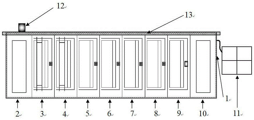
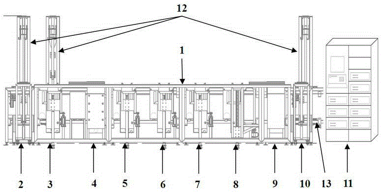
[0039] Embodiment 1: Fig. 1 (a) and (b) are the tank layout structure diagram of ultrasonic-megasonic composite water-based automatic cleaning device, (a) is a top view, (b) is a front view. It can be seen from Figure 1 that the device integrates water-based chemical solution cleaning, ultrasonic cleaning, megasonic cleaning, ultrapure water spraying, slow pulling dehydration and air knife drying technology to realize fully automatic cleaning of large-sized optical parts. The tank body has 7 slots and 2 workpiece loading and unloading areas from left to right, which are the cleaning tank frame 1, the workpiece loading area 2 (including the racking trolley shown in the figure), the solution soaking ultrasonic cleaning tank 3, and the spraying Slot 4, megasonic cleaning tank 5, first ultrasonic rinsing tank 6, second ultrasonic rinsing tank 7, megasonic rinsing and dehydration tank 8 and drying tank 9, workpiece unloading area 10, control cabinet 11, The workpiece moves the mech...


PUM


Abstract

The invention discloses a fully-automatic optical element cleaning device with an ultrasonic-megasonic composite frequency. The ultrasonic-megasonic composite frequency covers low/intermediate/high ultrasonic frequencies and low/intermediate/high megasonic frequencies. Particularly, an appropriate program and process parameters are selected to aim at super-clean washing requirements for an optical element, and pollutants from a micron scale to a nanometer scale on the surface of the optical element can be effectively removed. The fully-automatic optical element cleaning device with the ultrasonic-megasonic composite frequency has the main characteristics that an ultrasonic solution soaking cleaning tank, a megasonic cleaning tank and a spraying tank are designed; different frequency ultrasonic and megasonic waves are adopted, and cleaning requirements from a micron size to a nanometer size are covered; a workpiece is driven by a cylinder to reciprocate up and down in a tank body, a wave node of a standing wave field is prevented from being generated in a fixed area of the surface of the workpiece by virtue of a frequency sweeping function of an ultrasonic-megasonic generator, and the surface damage is avoided; the tank body adopts overflow cycle heating filtration; the total length of an overflow front edge is increased by using a trapezoidal saw-tooth type overflow edge design to obtain uniform and stable overflow; an inclined workpiece clamping device cooperates with an air knife and a slow lifting mechanism to dry the workpiece.

Description

technical field [0001] The invention relates to an ultrasonic-megasonic composite frequency fully automatic cleaning device for optical components, which is especially suitable for ultra-clean cleaning of large-sized, high-precision optical components. The frequency covers low, medium, high and megasonic frequencies and can effectively remove optical components. Organic and inorganic pollutants on the surface of components from micron to nanoscale. Background technique [0002] Modern high-precision optical systems have higher and higher requirements for the cleanliness of the surface of optical components. There are complex pollutants such as oil, particles, and human pollution on the surface of optical components processed by traditional conventional processes. In the development of laser gyroscopes, in order to increase the blocking threshold of the ring cavity, the high reflection plate of the ring cavity is required to have extremely low loss and high reflectivity, and ...

Claims


Application Information

Patent Timeline
IPC IPC(8): B08B3/10B08B3/12B08B3/02B08B3/14B08B11/00
CPCB08B3/02B08B3/10B08B3/123B08B3/14B08B11/00
Inventor 王占山沈正祥丁涛来颖江浩苏静崔勇
Owner TONGJI UNIV
Why Eureka
Try Eureka