
System state indicator

a system state and indicator technology, applied in the field of vehicles, can solve the problems of reducing the efficacy of the system to zero, unable to display data, and very low frequency of such incidents

Inactive Publication Date: 2006-07-18
MICHELIN RECH & TECH SA
View PDF12 Cites 19 Cited by
  • Summary
  • Abstract
  • Description
  • Claims
  • Application Information

AI Technical Summary

Benefits of technology

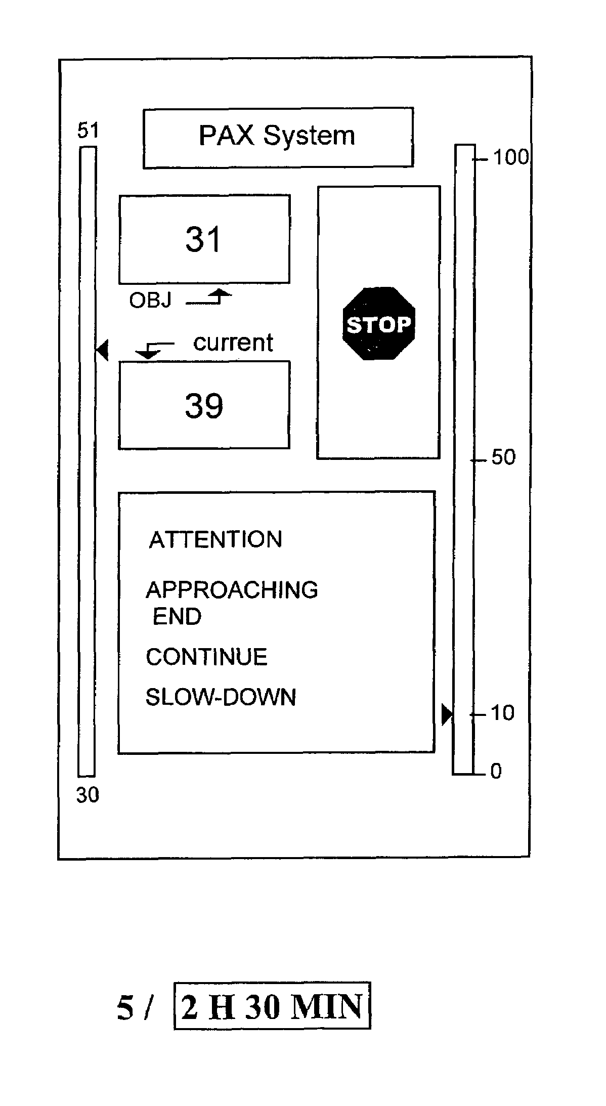
[0023]The display of the quantity C related to the severity of the conditions of use of the system, in addition to the potential of use and the range of use, enables the driver to know and follow a parameter which takes account of the influence of his driving on the state of the system. He can thus adapt his driving in order to obtain the range of use which is necessary to him.
[0030]Knowledge of the potential gives the driver simple information on the state of the system in question. The maximum and minimum possible values of the range of use of the system supplement this information and enable him to be continuously sufficiently informed of the possibilities of the system and thus of his vehicle.
[0039]The graduated range can also have a logarithmic scale of values. This has the advantage of focusing the attention of the driver on the small values at the end of life of the system.
[0045]A person skilled in the art knows that this “range of use” is a function of the driving mode adopted by the driver. The range of use at time t reflects the current value of this range, which results from the past driving mode. It is obviously that, with regard to the future, the range of use will be affected by the driving mode adopted. The invention thus has the advantage of integrating this parameter into the state indicator: this involvement of the “driving mode” parameter has the great advantage of allowing the definition, at a time t, of the MINIMUM range of use (in the case of abrupt driving mode) and MAXIMUM range of use (in the case of flexible driving mode). The invention therefore affords for the first time direct information on the range of use AND information on the minimum and maximum accessible, and therefore an explicit recommendation on the driving mode for the driver.
[0068]The advantage of such a system is using the same display mode for different functionalities, which enables the user to know and understand it clearly. Thus, when a fault, for example with one of the tires, occurs and the flat running system of the tire concerned is implemented, the user will immediately understand and apply the recommendations transmitted by the indicator.

Problems solved by technology

Moreover there exist new technical developments for which a data display is not possible at the present time.
The frequency of such incidents is very low and, if the displayed data is not immediately comprehensible, the driver may completely misunderstand the meaning of the data displayed and the changes therein, which may reduce the efficacy of the system to zero.
Another problem posed relates to the size of vehicle dashboards, as the number and sophistication of on-board systems increases.
A person skilled in the art will have understood that the above criteria and objectives are to a major extent clearly contradictory, which greatly complicates any search for a technical solution.
However, these displays are of a very simple type since they are limited to a single value whose meaning may not escape the driver.
Such a system was by nature extremely rudimentary and not very useful in practice.

Method used


Image

  • System state indicator
  • System state indicator
  • System state indicator

Examples


Embodiment Construction

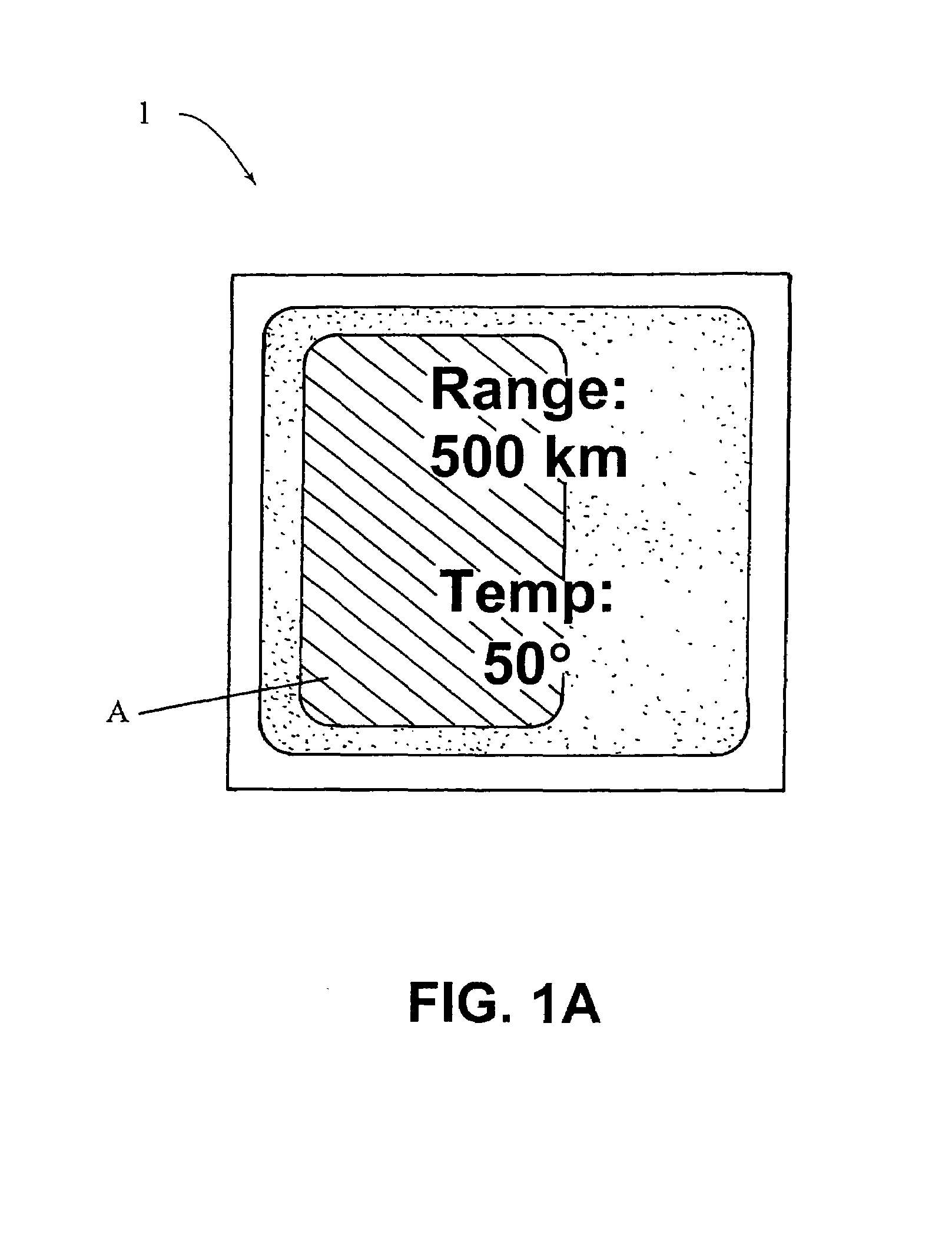
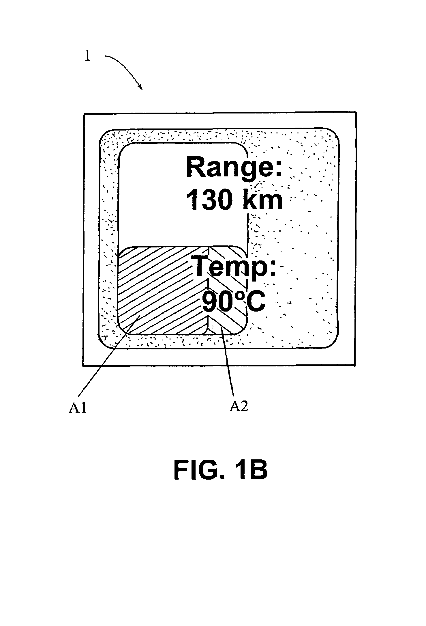
[0075]FIG. 1, which is composed of FIGS. 1A and 1B, depicts a non-limiting display screen 1 according to the invention, adapted to display the temperature of a tire in APL condition or flat running as well as the remaining range, that is the say the number of kilometers that the driver, at time t and under the driving conditions of this time, can travel without damaging or seriously degrading the tire. Such a display applies particularly to the PAX system.

[0076]It should be stated briefly that the PAX system consists essentially of a “support” made from material of the vulcanized rubber type or the like, mounted on a special rim profile. When a tire fails, the vehicle can continue to travel on the said “support”, which prevents damage to the tire sidewalls and in particular shearing thereof. For reasons of overheating and the like, well known to specialists in flat running, it is necessary to limit the speed of the vehicle.

[0077]This system is now well known and a person skilled in ...


PUM


Abstract

System state indicator in particular for a vehicle dashboard, the system having a given use potential and comprising evaluation means such that, on the basis of measurements related to the conditions of use of the vehicle and / or the physical characteristics of the system and / or the vehicle and / or the vehicle environment conditions, the evaluation means calculate at a time t parameters characteristic of the state of the system, characterized in that the state indicator simultaneously displays at time t at least three different parameters characteristic of the state of the system and its range.

Description

[0001]The present application is a continuation of International Application Serial No. PCT / EP03 / 03920 filed Apr. 15, 2003 and which claims priority of patent application Ser. No. 02 / 04965 filed in France on Apr. 18, 2002.BACKGROUND OF THE INVENTION[0002]The present invention concerns the technical sector of vehicles provided with tires and on-board electronic systems which relate to them.[0003]“Vehicles” will, throughout the present application, including the claims, mean both light vehicles (LV), such as private cars or vehicles, and utility vehicles or heavy vehicles such as lorries and “heavy goods vehicles” (HGVs), trailers, forestry vehicles, construction machinery, military or emergency vehicles, and the like.[0004]The electronic systems on board vehicles are becoming more and more numerous and of higher and higher performance, and deliver more and more data for the driver.[0005]Moreover there exist new technical developments for which a data display is not possible at the pr...

Claims


Application Information

Patent Timeline
Patent Type & Authority Patents(United States)
IPC IPC(8): G08B21/00B60C23/00G01D7/00G01D7/02
CPCG01D7/02G01D7/002B60L2250/16
Inventor HOTTEBART, FRANCOISSHEPHERD, RUSSELBOUIGES, THIERRY
Owner MICHELIN RECH & TECH SA
Learn More