
Cryptographic key split binding process and apparatus

a technology of cryptographic keys and splits, applied in the field of cryptographic systems, can solve the problems of difficulty in defeating cryptography, message is worthless to the interloper, and wireless transmission,

Inactive Publication Date: 2006-07-18
TECSEC
View PDF47 Cites 44 Cited by
  • Summary
  • Abstract
  • Description
  • Claims
  • Application Information

AI Technical Summary

Benefits of technology

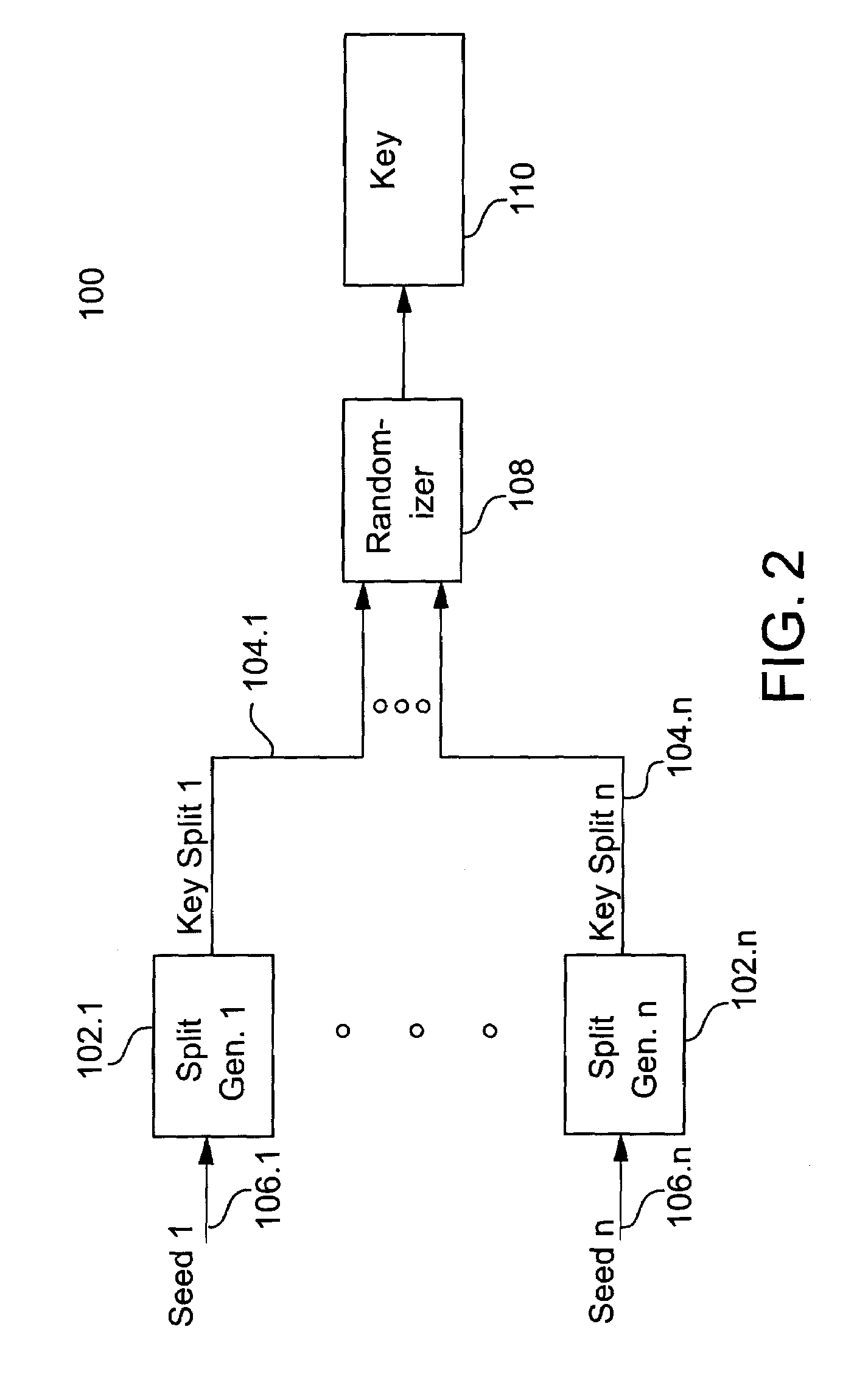
"The present invention provides a process and apparatus for assembling keys that provides added security against unauthorized entities. This is achieved by generating a cryptographic key split based on seed data and randomizing the key splits to produce a cryptographic key. The seed data can be based on location, such as a geographic location or a network location. The process can also include receiving the location seed data from a geographic location device or a computer network. The invention provides a more secure way to communicate using cryptographic keys."

Problems solved by technology

Unfortunately, drawbacks accompany the benefits provided by electronic communication, particularly in the area of privacy.
Wireless transmissions, such as voice communication by cellular telephone, and electronic mail are especially susceptible to such interception.
If the communication is intercepted during transmission or is extracted from storage by an unauthorized entity, the message is worthless to the interloper, who does not possess the means to decrypt the encrypted message.
An important consideration in determining whether a particular cryptographic scheme is adequate for the application is the degree of difficulty necessary to defeat the cryptography, that is, the amount of effort required for an unauthorized person to successfully decrypt the encrypted message.
The more difficult it is for an unauthorized person to obtain a valid key, the more secure communications will be under a particular scheme.

Method used


Image

  • Cryptographic key split binding process and apparatus
  • Cryptographic key split binding process and apparatus
  • Cryptographic key split binding process and apparatus

Examples


Embodiment Construction

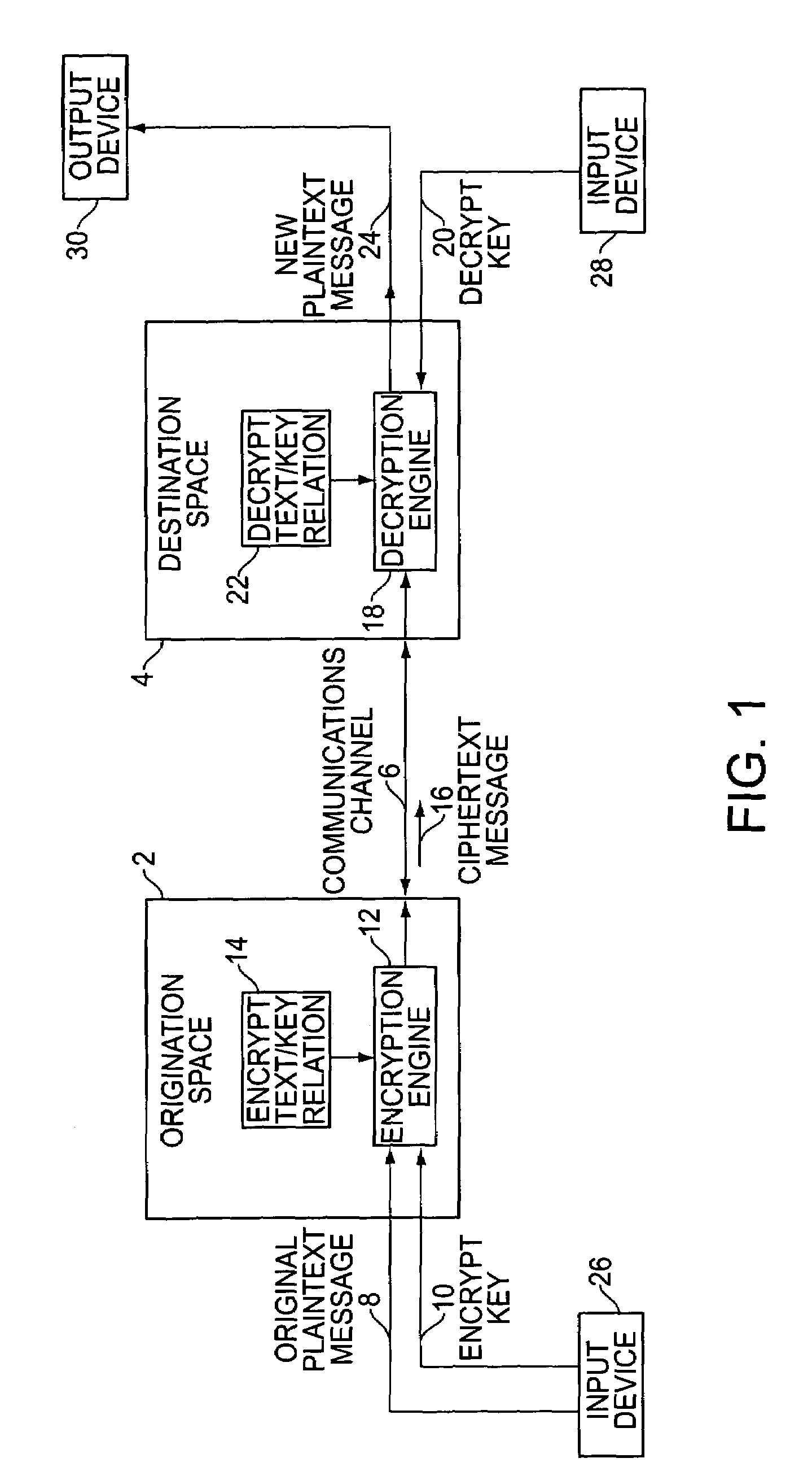
[0023]Referring to FIG. 1, a communication has an origination space 2 and a destination space 4. The origination space 2 defines the place and time at which the communication originates. The destination space 4 defines the place and time at which the communication is intended to be decoded. The origination space 2 and the destination space 4 can be remote in location. Alternatively, they can be collocated but displaced in time. The space and time correspondence between the origination space 2 and the destination space 4 depends on the nature of a particular communication. The origination space 2 and destination space 4 are coupled to a common communications channel 6. This communications channel 6 can bridge a physical space, such as empty air in the case of a cellular voice telephone call. Alternatively, the communications channel6 can be temporary storage for the communication while time passes between the origination space 2 and the destination space 4, such as a message left in ...


PUM


Abstract

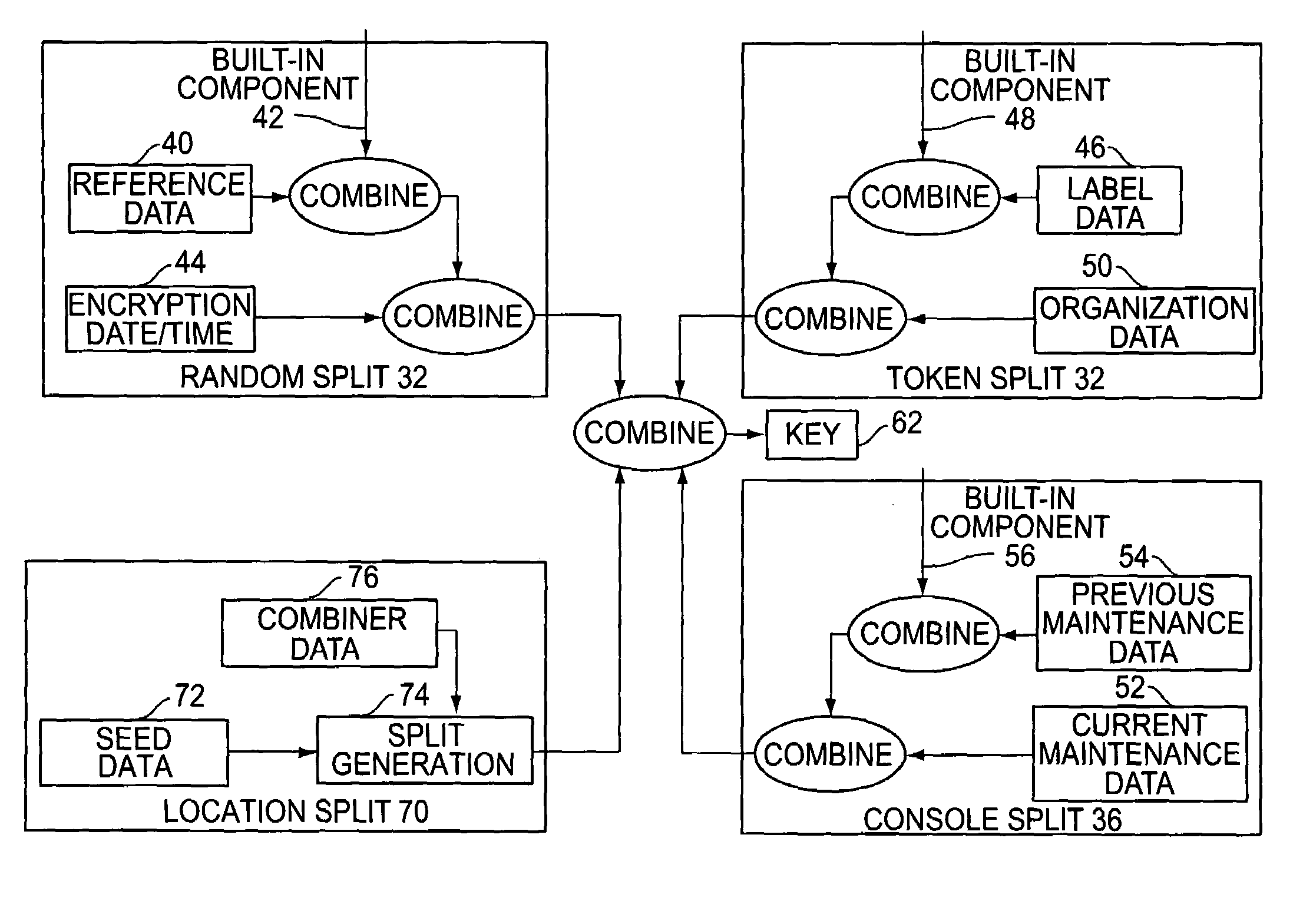
A cryptographic key split combiner includes a number of key split generators for generating cryptographic key splits from seed data, and a key split randomizer for randomizing the key splits to produce a cryptographic key. The key split generators can include a random split generator for generating random key splits, a token split generator for generating token key splits based on label data, a console split generator for generating console key splits based on maintenance data, a biometric split generator for generating biometric key splits based on biometric data, and a location split generator for generating location key splits based on location data. Label data can be read from storage, and can include user authorization data. A process for forming cryptographic keys includes randomizing or otherwise binding the splits to form the key.

Description

CROSS-REFERENCE TO RELATED PATENTS AND APPLICATIONS[0001]This is a continuation-in-part of U.S. patent application Ser. No. 09 / 023,672, which was filed on Feb. 13, 1998 now U.S. Pat. No. 6,885,747, the disclosure of which is incorporated herein by reference. This also claims priority from U.S. Provisional Patent Application No. 60 / 352,123, which was filed on Jan. 24, 2002. This disclosure is related to the following issued U.S. Pat. No. 5,375,169, entitled “Cryptographic Key Management Method and Apparatus,” which issued on Dec. 20, 1994 to SCHEIDT et al.; and U.S. Pat. No. 5,787,173, entitled “Cryptographic Key Management Method and Apparatus,” which issued on Jul. 28, 1998 to SCHEIDT et al. This disclosure is also related to the following co-pending U.S. patent applications: Ser. No. 09 / 874,364, entitled “Cryptographic Key Split Combiner,” which was filed on Jun. 6, 2001 by SCHEIDT et al.; Ser. No. 09 / 917,795, entitled “Cryptographic Key Split Combiner,” which was filed on Jul. 31...

Claims


Application Information

Patent Timeline
Patent Type & Authority Patents(United States)
IPC IPC(8): H04L9/14H04L9/24H04L9/08
CPCH04L9/0869H04L9/085
Inventor SCHEIDT, EDWARD M.WACK, C. JAY
Owner TECSEC
Learn More