Frequency compander for a telephone line

a technology of telephone lines and frequency companders, which is applied in the field of frequency extenders for telephone lines, can solve the problems of the original signal signal signal signal-to-noise ratio suffering degradation

Inactive Publication Date: 2006-07-18
FISHER KEN SCOTT +2
View PDF6 Cites 3 Cited by
  • Summary
  • Abstract
  • Description
  • Claims
  • Application Information

AI Technical Summary

Benefits of technology

[0026]Further objects, features, and advantages of the present invention will be apparent to those skilled in the art upon examining the accompanying drawings and upon reading the following description of the preferred embodiments.

Problems solved by technology

The companding process is not without its costs, the signal-to-noise ratio of the original signal suffers degradation due to phase noise arising in the companding process and through lost resolution in the noise floor of the signal.

Method used


Image

  • Frequency compander for a telephone line
  • Frequency compander for a telephone line
  • Frequency compander for a telephone line

Examples


Embodiment Construction

[0034]Before explaining the present invention in detail, it is important to understand that the invention is not limited in its application to the details of the construction illustrated and the steps described herein. The invention is capable of other embodiments and of being practiced or carried out in a variety of ways. It is to be understood that the phraseology and terminology employed herein is for the purpose of description and not of limitation.

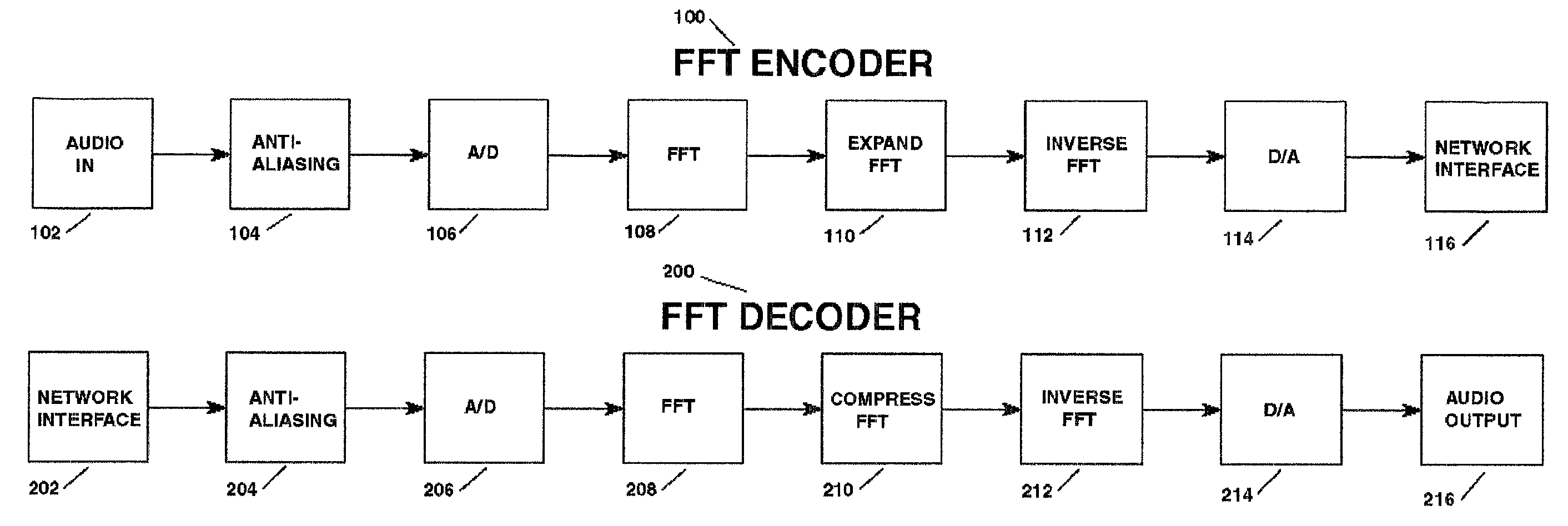
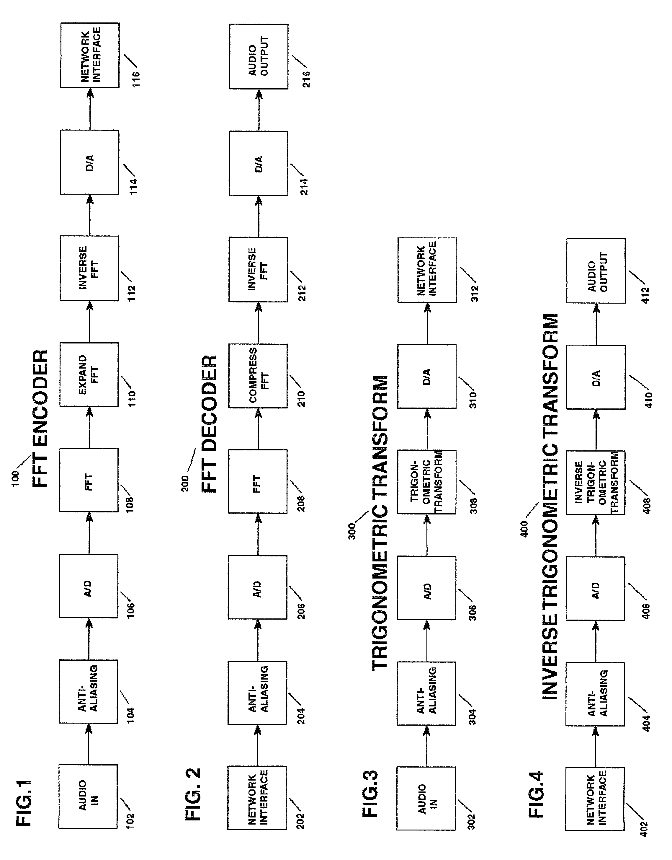
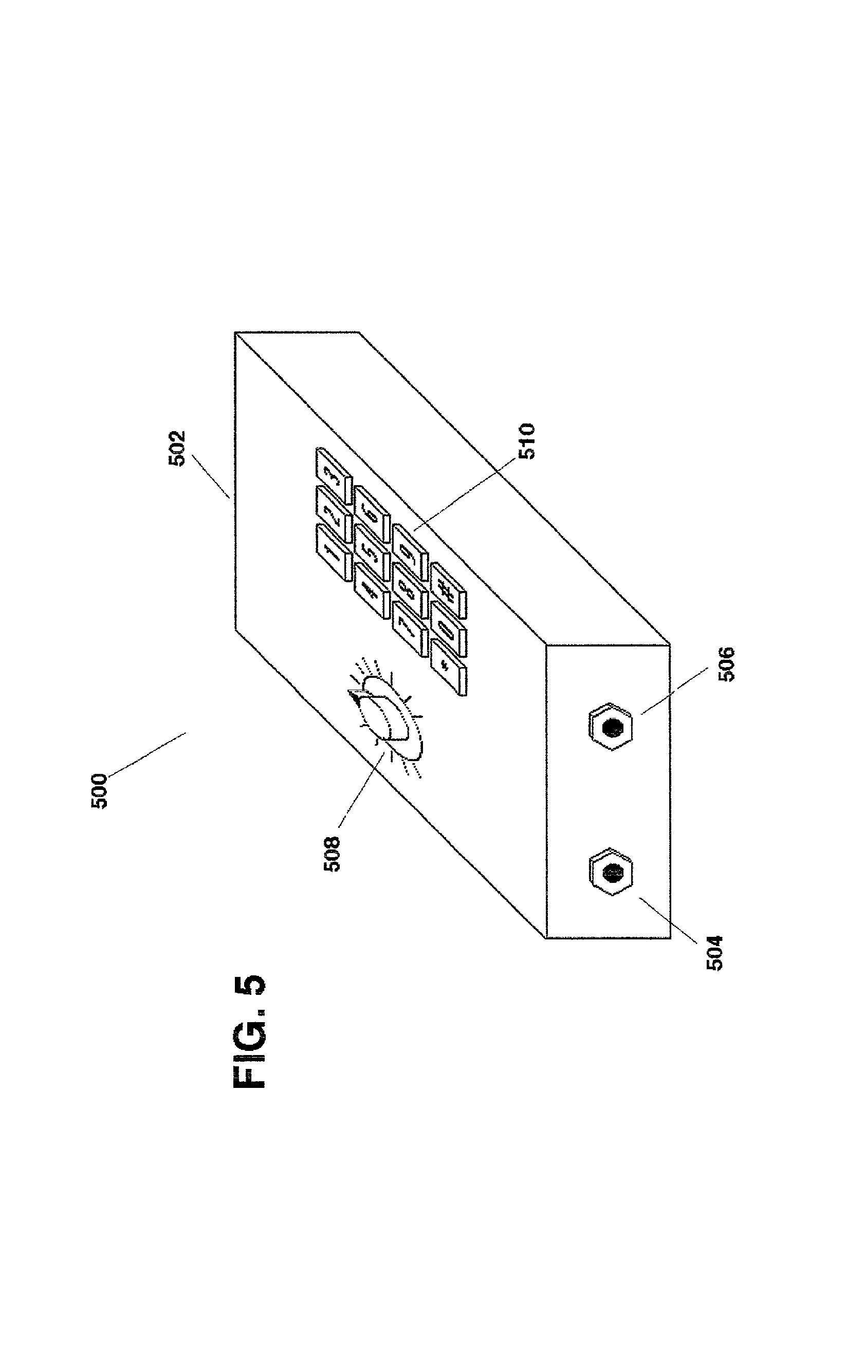
[0035]Referring now to the drawings, wherein like reference numerals indicate the same parts throughout the several views, a typical frequency compander 500 is shown in FIG. 5. Preferably, compander 500 comprises: enclosure 502; microphone jack 504, typically an industry standard 3-pin XLR connector for the connection of a microphone 602 (FIG. 6), or other audio source; a headphone jack 506, typically a ¼ inch phone jack for the connection of a pair of headphones 604 (FIG. 6); a knob 508 for adjusting the volume of the audio sent to h...


PUM


Abstract

A frequency compander for improving the frequency response of a telephone line when used for remote broadcasting. The inventive device comprises an encoder for compressing the frequency spectrum of an audio signal and a decoder for expanding the signal back to its original spectrum. Preferably the encoder comprises: an anti-aliasing filter; an A/D converter for digitizing incoming audio; a DSP for compressing the audio; and a D/A converter for outputting compressed audio to the phone line. The decoder comprises: an anti-aliasing filter; an A/D converter for digitizing the incoming compressed signal; a DSP for restoring the original audio; and a D/A converter for outputting program audio. In a preferred embodiment, encoding and decoding are performed in the frequency domain. In another preferred embodiment, encoding and decoding are performed in the time domain using trigonometric transformations.

Description

BACKGROUND OF THE INVENTION[0001]1. Field of the Invention[0002]The present invention relates to frequency extenders for a telephone line. More particularly, but not by way of limitation, the present invention relates to a frequency extender to expand the bandwidth of a dialup telephone line used to carry remote audio programming.[0003]2. Background of the Invention[0004]Virtually every broadcaster, whether radio or television, has at some point in time, felt the need to carry programming originating from a remote location. In response to this need, a number of solutions have been developed. Unfortunately, every method presently used for remote broadcasting suffers from its own set of disadvantages.[0005]Presently radio frequency devices are the favored method for sending programming from a remote location to a studio or transmitter for broadcast. Devices offered for this purpose are often referred to as a “remote pickup unit” or “RPU.”[0006]Perhaps the favored RPU is a microwave li...

Claims


Application Information

Patent Timeline
Patent Type & Authority Patents(United States)
IPC IPC(8): G10L21/04G10L19/02G10L19/08G10L21/00
CPCG10L19/02G10L19/093
Inventor FISHER, KEN SCOTTBAXTER, KEVIN COTTONHOLMES, FRED H.
Owner FISHER KEN SCOTT
Why Eureka
Try Eureka