Oscillator

a technology of oscillator and oscillator circuit, which is applied in the direction of oscillator generator, pulse generator, pulse technique, etc., can solve the problems of delay, frequency precision is still affected by other external factors, and the frequency precision of the common rc oscillator circuit is mainly limited, so as to reduce the effect of temperature and less dependency on power supply

Active Publication Date: 2021-02-25
SHANGHAI HUALI MICROELECTRONICS CORP
View PDF0 Cites 3 Cited by
  • Summary
  • Abstract
  • Description
  • Claims
  • Application Information

AI Technical Summary

Benefits of technology

[0036]In the oscillator of the present invention, the RC oscillator 10 is selected as a frequency generating module, and since the oscillation frequency of the RC oscillator 10 has less dependency on a power supply, a clock source having a relatively precise frequency thus can be obtained; and based on the RC oscillator 10, the bandgap reference source 30 having a temperature compensation function is added, the reference current IREF generated by the bandgap reference source 30 with an adjustable temperature coefficient is used for temperature coefficient compensation to the inherent temperature coefficient of the oscillation frequency of the RC oscillator 10, thereby reducing the effect of the temperature on the oscillator, so that the output frequency of the oscillator does not change with the temperature as far as possible, which improves the oscillation frequency precision of the oscillator.

Problems solved by technology

In a half cycle, a delay is caused by charge and discharge of a capacitor using a unilateral current.
The oscillation frequency precision of the common RC oscillator circuit is mainly limited by the temperature drift of a CMOS device.
Although the common RCOSC (RC oscillator) circuit is basically independent of the power supply, the frequency precision is still affected by other external factors, such as the temperature and process.

Method used


Image

  • Oscillator
  • Oscillator
  • Oscillator

Examples


embodiment 1

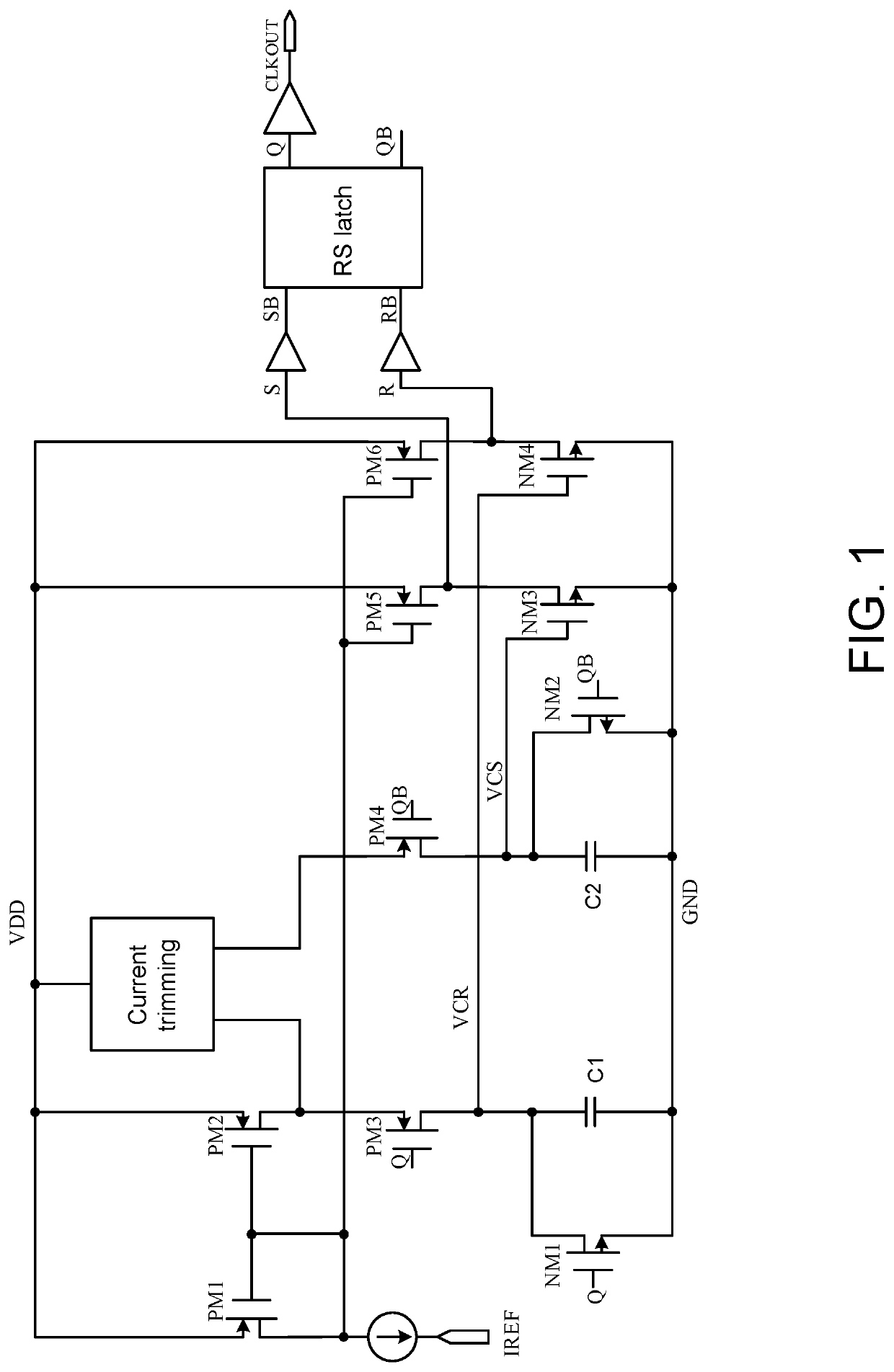
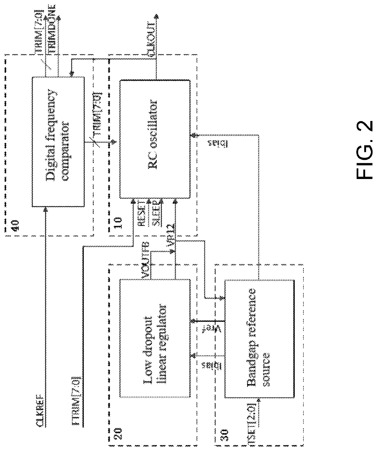
[0043]As shown in FIG. 2, an oscillator comprises an RC oscillator 10 and a bandgap reference source 30.

[0044]The bandgap reference source 30 provides a reference current IREF for the RC oscillator 10.

[0045]A temperature coefficient of the reference current output by the bandgap reference source 30 is adjustable.

[0046]Preferably, the temperature coefficient of the reference current output by the bandgap reference source 30 is opposite to a temperature coefficient of an oscillation frequency output by the RC oscillator 10.

[0047]Preferably, both the RC oscillator 10 and the bandgap reference source 30 are semiconductor devices manufactured by mean of a CMOS process.

[0048]Preferably, the RC oscillator 10 and the bandgap reference source 30 are on the same substrate.

[0049]In the oscillator of embodiment 1, the RC oscillator 10 is selected as a frequency generating module, and since the oscillation frequency of the RC oscillator 10 has less dependency on a power supply, a clock source ha...

embodiment 2

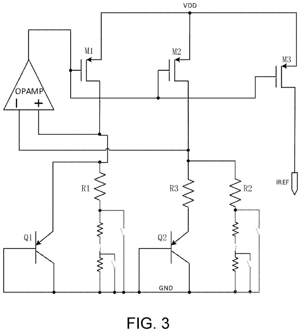
[0050]Based on the oscillator of embodiment 1, as shown in FIG. 3, the bandgap reference source 30 comprises an operational amplifier OPAMP, a first PMOS transistor M1, a second PMOS transistor M2, a third PMOS transistor M3, a first PNP transistor Q1, a second PNP transistor Q2, a first resistor R1, a second resistor R2, and a third resistor R3.

[0051]The resistances of the first resistor R1 and the second resistor R2 are adjustable.

[0052]An output of the operational amplifier OPAMP is connected to gates of the first PMOS transistor M1, the second PMOS transistor M2, and the third PMOS transistor M3.

[0053]Source terminals of the first PMOS transistor M1, the second PMOS transistor M2, and the third PMOS transistor M3 are connected to a working voltage VDD.

[0054]A drain terminal of the first PMOS transistor M1 and an emitter of the first PNP transistor Q1 are connected to a positive input end of the operational amplifier OPAMP.

[0055]The first resistor R1 is connected between the posi...

embodiment 3

[0065]Based on embodiment 1, the oscillator further comprises a low dropout linear regulator 20.

[0066]The low dropout linear regulator 20 provides a working voltage source for the RC oscillator 10 and the bandgap reference source 30.

[0067]Preferably, the bandgap reference source 30 further provides the reference current IREF and a reference voltage VREF for the low dropout linear regulator 20.

[0068]The low dropout linear regulator (LDO) is a micro-power low dropout linear regulator that generally has extremely low self-noise and a relatively high power supply rejection ratio (PSRR). The low dropout linear regulator is a new generation of an integrated circuit regulator and differs from a three terminal regulator mainly in that the low dropout linear regulator is a system on chip (SOC) with very low self-consumption, which can be used for controlling a main channel of a current, with the chip being integrated with a MOSFET with extremely low on-resistance and hardware circuits such a...


PUM


Abstract

An oscillator comprising an RC oscillator and a bandgap reference source, wherein the bandgap reference source provides a reference current for the RC oscillator, and a temperature coefficient of the reference current is adjustable. Since the oscillation frequency of the RC oscillator has less dependency on a power supply, a clock source having a relatively precise frequency thus can be obtained; and based on the RC oscillator, the bandgap reference source having a temperature compensation function is added, the reference current generated by the bandgap reference source with an adjustable temperature coefficient is used for temperature coefficient compensation to the inherent temperature coefficient of the oscillation frequency of the RC oscillator, thereby reducing the effect of the temperature on the oscillator, so that the output frequency of the oscillator does not change with the temperature as far as possible, which improves the oscillation frequency precision of the oscillator.

Description

CROSS REFERENCE TO RELATED APPLICATIONS[0001]The present application claims priority to and the benefit of Chinese Patent Application No. 201910777059.4 filed on Aug. 22, 2019, the disclosure of which is incorporated herein by reference in its entirety as part of the present application.BACKGROUND[0002]The invention relates to integrated circuit design, in particular to an oscillator.[0003]A common RC oscillator circuit, which has a current steering structure, is shown in FIG. 1. In a half cycle, a delay is caused by charge and discharge of a capacitor using a unilateral current. Since the outputs Q and QB of an RS latch are inverted signals, it can ensure that the left and right switches (PM3, PM4, NM1, NM2) do not turn off at the same time, avoid the non-ideal effect of switching capacitor such as charge injection, which causes an R-controlled voltage VCR or S-controlled voltage VCS to jump. Due to use of an RS flip-flop with logic gate control, charge and discharge times of the t...

Claims


Application Information

Patent Timeline
Patent Type & Authority Applications(United States)
IPC IPC(8): H03B5/04H03B5/24
CPCH03B5/04H03B5/24H03B5/1237H03K3/0231H03K3/011
Inventor ZHANG, NINGZHU, XUANLIWANG, ZHILI
Owner SHANGHAI HUALI MICROELECTRONICS CORP
Why Eureka
Try Eureka