

Device and method for measurement of ultrasonic transit times
a technology of ultrasonic wave and transit time, which is applied in the direction of measurement devices, instruments, testing/calibration apparatus, etc., can solve the problems of inability to accurately and reliably measure the transit time, the strength of the received signal and the predefined threshold value is subject to electronic noise, and the flow velocity changes not only with flow velocity, but also with fluid properties and electronic noise levels. , to achieve the effect of improving the velocity measurement accuracy of ultrasonic flow sensors, accurate and reliable measuremen
- Summary
- Abstract
- Description
- Claims
- Application Information
AI Technical Summary
Benefits of technology
Problems solved by technology
Method used
Image

Examples
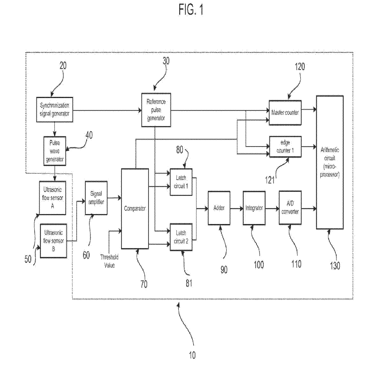
first embodiment
Obviously, the transit-time Tm obtained by prior art differs from the one obtained by the present disclosure by N1Tr / 2. This difference does not have any impact on the flow measurement, because the flow rate is calculated based on transit-time difference between upstream Tm and downstream Tm. In addition, the difference can be calibrated so to have accurate transit-time measurement.
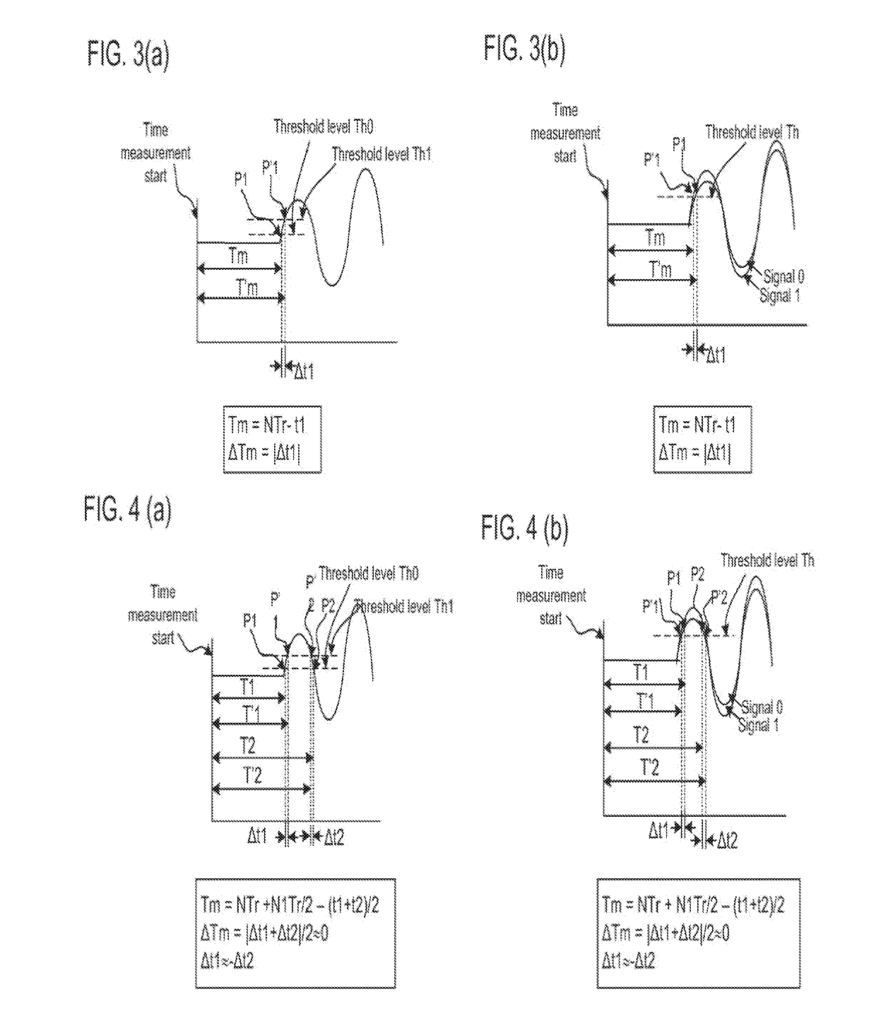
[0045]FIG. 3 (a) illustrates the transit time measurement error caused by the threshold level fluctuation of prior art. In this case the time measurement error is:
ΔTm=|Δt1|.
[0046]FIG. 3 (b) illustrates the transit time measurement error caused by signal amplitude fluctuation of prior art. In this case the time measurement error is:
ΔTm=|Δt1|.
[0047]FIG. 4(a) illustrates the transit time measurement error caused by threshold fluctuation of the first embodiment of the present disclosure. In this case the time measurement error is:
ΔTm=|Δt1+Δt2| / 2.
[0048]FIG. 4(b) illustrates the transit time measurement error c...
PUM
 Abstract
Description
Claims
Application Information