Device and method for measurement of ultrasonic transit times

a technology of ultrasonic wave and transit time, which is applied in the direction of measurement devices, speed/acceleration/shock measurement devices, instruments, etc., can solve the problems of affecting the accuracy of ultrasonic flow sensors, the strength of received signals and predefined threshold values is subject to electronic noise, and the transit time changes not only with flow velocity, but also with fluid properties and electronic noise levels. , to achieve the effect of accurate and reliable measurement of transit times, improving the velocity measurement accuracy of ultra

Inactive Publication Date: 2014-04-10
SPIRE METERING TECH
View PDF4 Cites 6 Cited by
  • Summary
  • Abstract
  • Description
  • Claims
  • Application Information

AI Technical Summary

Benefits of technology

[0011]The object of the present invention is to provide an electronic device which can accurately and reliably measure the transit times from the transmitter to the receiver and hence improving the velocity measurement accuracy of an ultrasonic flow sensor.
[0012]In more detail the present invention provides an electronic device for measurement of ultrasonic wave transit times of an ultrasonic flow sensor consists of: 1) a synchronization signal generator, 2) a reference pulse generator, 3) a sine wave generator, 4) an analog signal amplifier, 5) a comparator, 6) a plurality of latch circuits, 7) a digital adder, 8) an integrator, 9) an A / D converter, 10) a master counter, 11) a plurality of edge counters, and 12) an arithmetic circuit (microprocessor). The device measures the ultrasonic wave transit times using a threshold level to trigger both the rising edge and falling edge of the received ultrasonic signal, and using a method of averaging the ultrasonic wave arriving times at different measuring points. This method has less dependency on the threshold level and the ultrasonic signal amplitude, thus, has less dependency on threshold drift, threshold stability, system gain fluctuation, electronic noise and signal amplitude variations. As a result, this method can greatly improve the velocity measurement accuracy and system robustness of an ultrasonic flow sensor.

Problems solved by technology

However, this measurement method is susceptible to electronic noise and condition variation.
Both the strength of the received signal and the predefined threshold value are subject to electronic noise.
As a result, the measured transit time changes not only with flow velocity, but with the fluid properties and electronic noise level.
This significantly reduces the velocity measurement accuracy and stability of an ultrasonic flow sensor.

Method used


Image

  • Device and method for measurement of ultrasonic transit times
  • Device and method for measurement of ultrasonic transit times
  • Device and method for measurement of ultrasonic transit times

Examples


first embodiment

Tm=NTr−t1.[0045]Obviously, the transit-time Tm obtained by prior art differs from the one obtained by the present disclosure by N1Tr / 2. This difference does not have any impact on the flow measurement, because the flow rate is calculated based on transit-time difference between upstream Tm and downstream Tm. In addition, the difference can be calibrated so to have accurate transit-time measurement.

[0046]FIG. 3 (a) illustrates the transit time measurement error caused by the threshold level fluctuation of prior art. In this case the time measurement error is:

ΔTm=|Δt1|.

[0047]FIG. 3 (b) illustrates the transit time measurement error caused by signal amplitude fluctuation of prior art. In this case the time measurement error is:

ΔTm=|Δt1|.

[0048]FIG. 4(a) illustrates the transit time measurement error caused by threshold fluctuation of the first embodiment of the present disclosure. In this case the time measurement error is:

ΔTm=|Δt1+Δt2| / 2.

[0049]FIG. 4(b) illustrates the transit time mea...

second embodiment

[0073]FIG. 7 illustrates the transit time measurement error of the present disclosure. In this case the time measurement error is:

ΔTm=|Δt1+Δt2+Δt3+Δt4| / 4.

Since (Δt1, Δt2) and (Δt3, Δt4) change in opposite directions, their average is always smaller than |t1|. This indicates that the ultrasonic wave transit time measurement accuracy is greatly improved using the method of the present disclosure compared to the method of prior art.

third embodiment

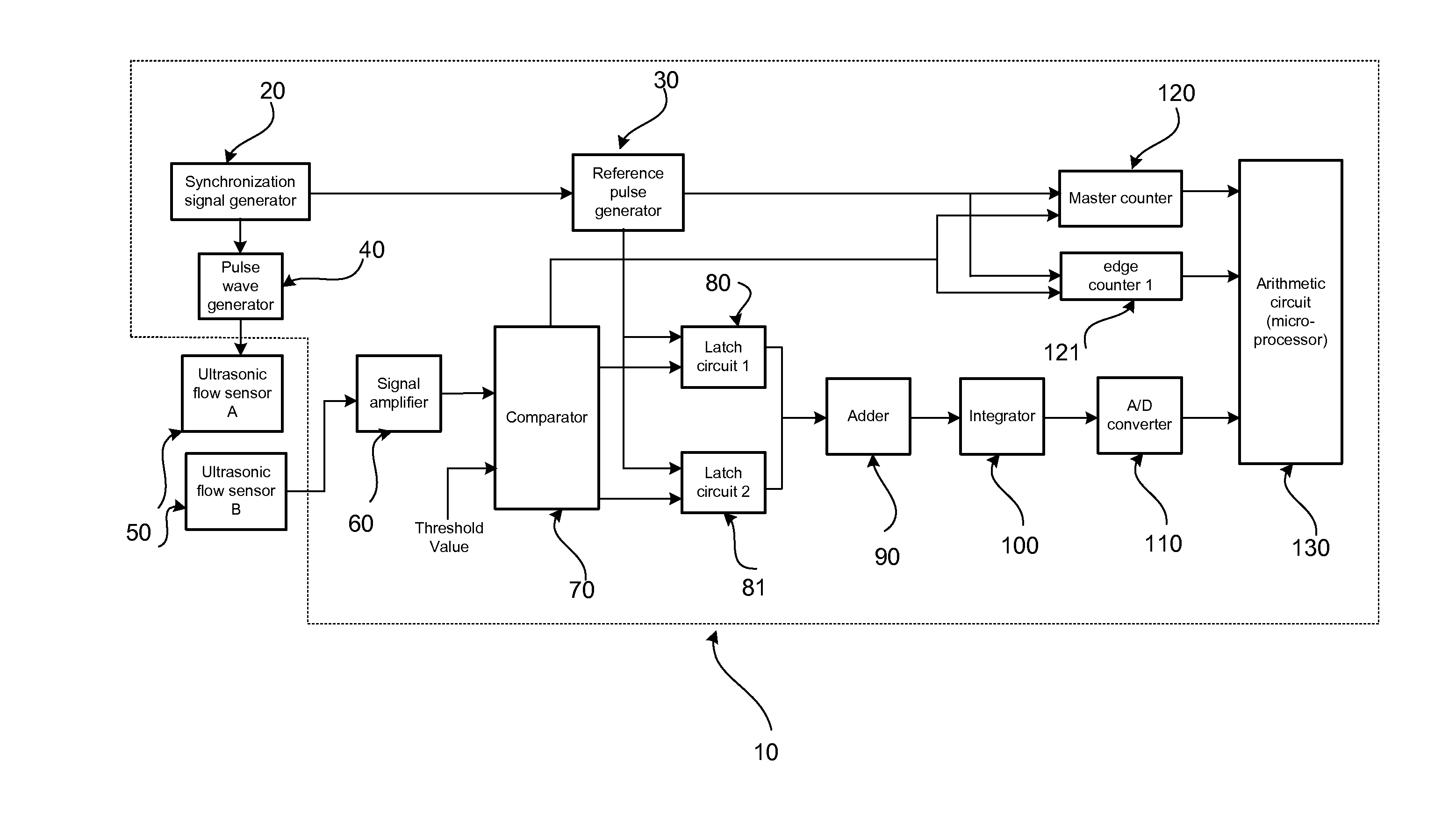
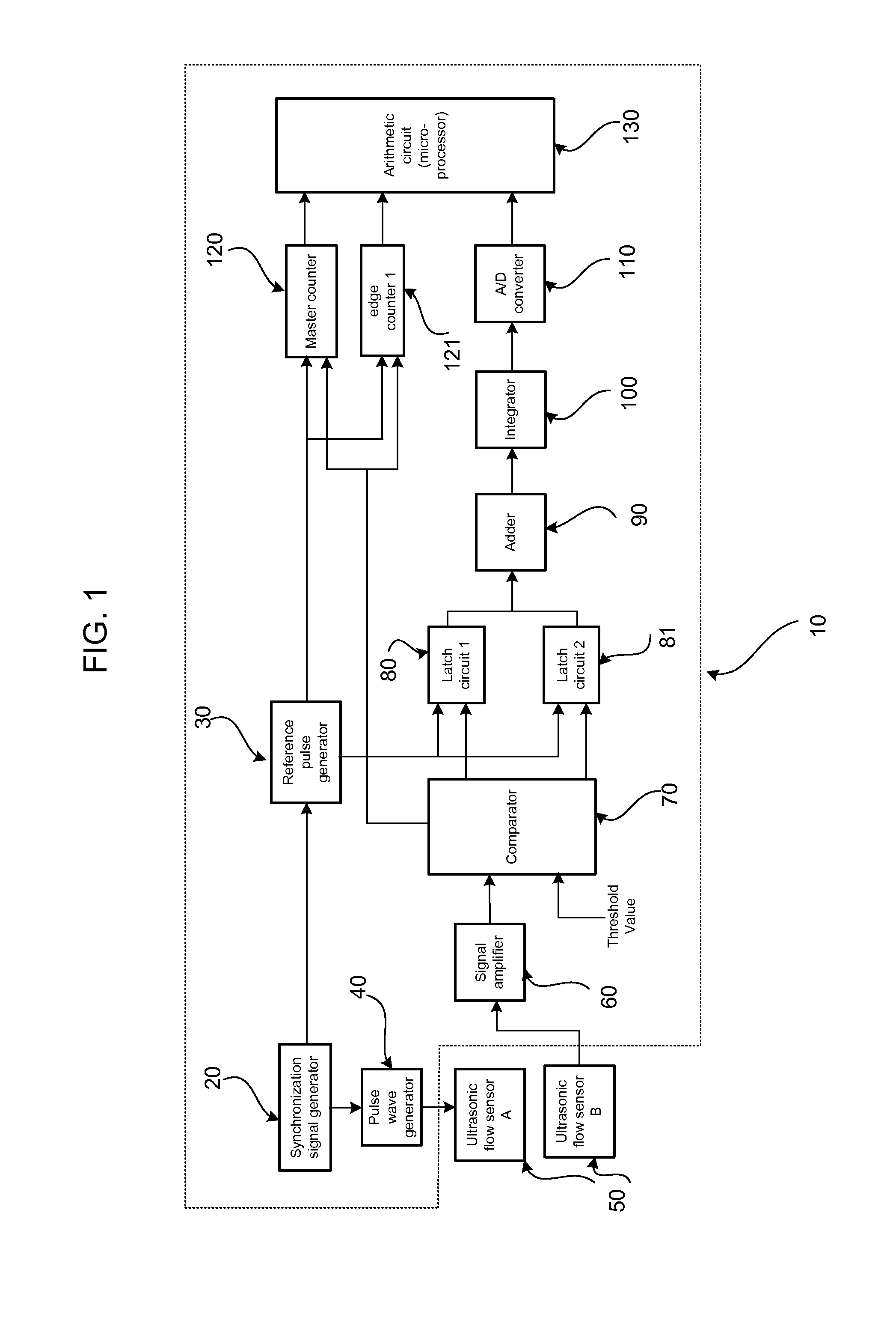
[0074]FIG. 8 illustrates an electronic device for measuring the ultrasonic wave transit times of the present disclosure. In this embodiment, the device 10 consists of a synchronization signal generator 20, a reference pulse generator 30, a sine wave generator 40, an analog signal amplifier 60, a comparator 70, eight latch circuits 80-87, a digital adder 90, an integrator 100, an A / D converter 110, a master counter 120, seven edge counters 121-127, and an arithmetic circuit 130.

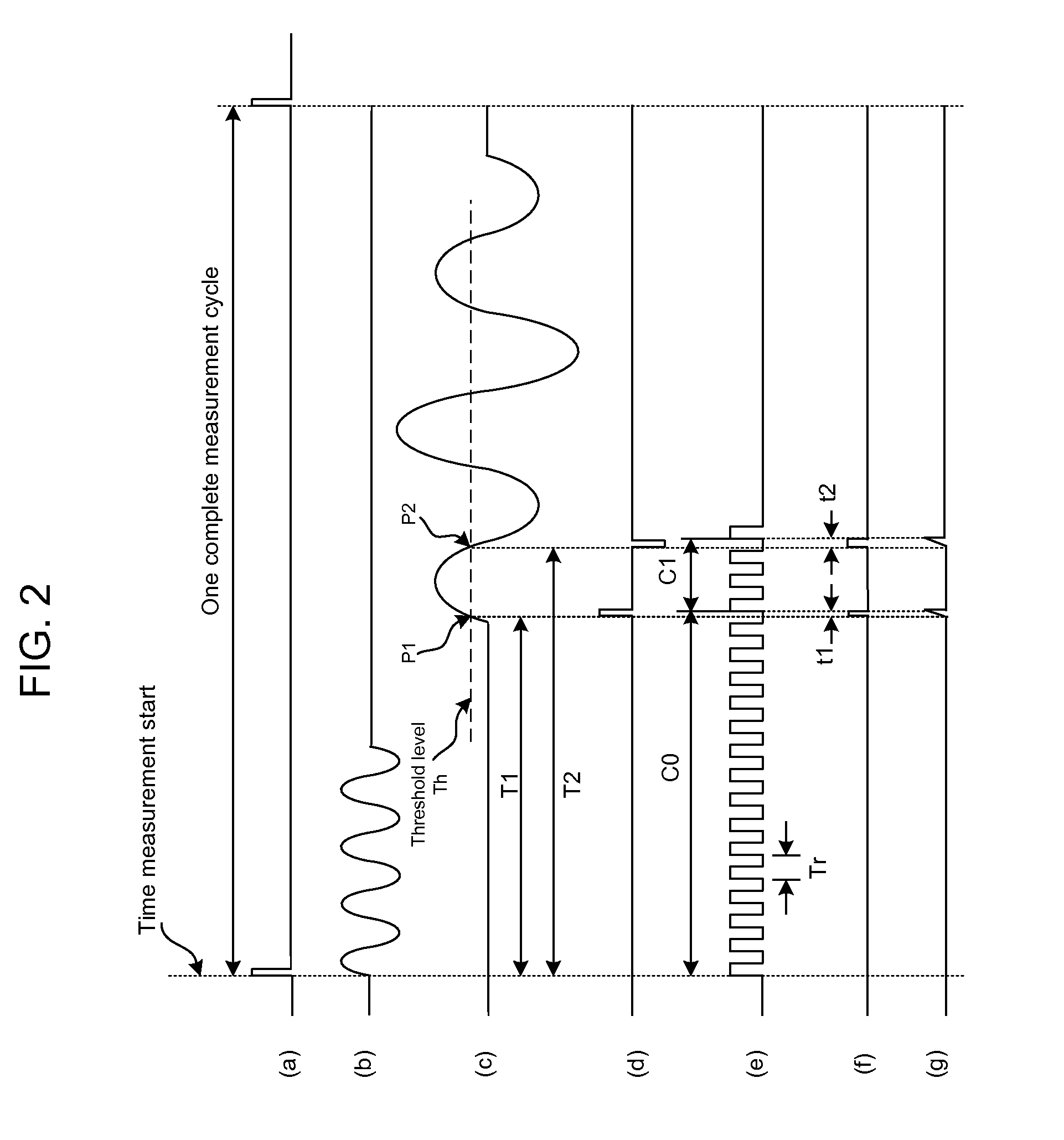
[0075]Referring to FIGS. 8 and 9, the synchronization signal generator 20 outputs a pulse shown in FIG. 9a. This pulse is used to perform the following functions: 1) initiating the measurement cycle, 2) triggering the sine wave generator 40 to start sending sine wave signal to the transmitter of the ultrasonic flow sensor 50, 3) triggering the reference pulse generator 30 to start generating high frequency clock signal, and 4) commanding the master counter 120 to start counting the reference clock cycles.

[0076...


PUM


Abstract

A device for measurement of ultrasonic wave transit times of an ultrasonic flow sensor consists of: 1) a synchronization signal generator, 2) a reference pulse generator, 3) a sine wave generator, 4) an analog signal amplifier, 5) a comparator, 6) a plurality of latch circuits, 7) a digital adder, 8) an integrator, 9) an A / D converter, 10) a master counter, 11) a plurality of edge counters, and 12) an arithmetic circuit. The device measures the ultrasonic wave transit times using a method of averaging the ultrasonic wave arriving times at different measuring points (triggering point). This method has less dependency on triggering threshold level and the ultrasonic signal amplitude, and thus has less dependency on threshold drift, threshold stability, system gain fluctuation, electronic noise and signal amplitude variations. As a result, the method can greatly improve the velocity measurement accuracy and system robustness of an ultrasonic flow sensor.

Description

CROSS-REFERENCE TO RELATED APPLICATIONS[0001]Not Applicable.STATEMENT REGARDING FEDERALLY SPONSORED RESEARCH OR DEVELOPMENT[0002]Not Applicable.REFERENCE TO SEQUENCE LISTING, A TABLE, OR A COMPUTER PROGRAM LISTING COMPACT DISC APPENDIX[0003]Not Applicable.FIELD OF THE INVENTION[0004]The present disclosure relates to a device for measuring ultrasonic wave transit times from the transmitter to the receiver of an ultrasonic flow sensor.BACKGROUND OF THE INVENTION[0005]The statements in this section merely provide background information related to the present disclosure and may not constitute prior art.[0006]An ultrasonic flow sensor measures the average velocity of liquid or gaseous media by means of ultrasonic transducers based on the principle that the transit time of an ultrasonic wave from the transmitter of a transducer to the corresponding receiver is determined by the fluid velocity and the ultrasonic wave propagating direction. Normally, a pair of transducers is used, one is in...

Claims


Application Information

Patent Timeline
Patent Type & Authority Applications(United States)
IPC IPC(8): G01F25/00
CPCG01F25/00
Inventor SHEN, CHANG
Owner SPIRE METERING TECH
Why Eureka
Try Eureka