Laser augmented turbojet propulsion system

a technology of propulsion system and laser, which is applied in the direction of efficient propulsion technology, machines/engines, light and heating apparatus, etc., can solve the problems of limited use and application, lack of power required to actuate the laser, and low thermal management requirements of fiber laser systems. achieve the effect of increasing thermal activity

Inactive Publication Date: 2006-07-25
NORTHROP GRUMMAN SYST CORP
View PDF26 Cites 15 Cited by
  • Summary
  • Abstract
  • Description
  • Claims
  • Application Information

AI Technical Summary

Benefits of technology

[0012]In a second embodiment, the turbojet propulsion system includes a combustion section that includes a plurality of hollow cylinders formed into a ring, each having a centrally located longitudinal axis. The inner surface of the cylinders include a laser beam reflecting surface. The lasers are positioned on the external surfaces of each of the cylinders to direct laser beams into the cylinders such that the laser beams are reflected off the inner surface of the cylinder. Preferably the lasers are positioned on the external surface of the cylinders such that the laser beams do not pass through the longitudinal axis of the cylinders. The Fiber laser output ends can act as one way mirrors, in that light may pass through into the combustion cylinders, however reflected laser light may not be allowed back, so as to prevent damage to the laser beam output optics.

Problems solved by technology

These next generation fiber laser systems require minimal thermal management and possess a relatively small footprint within an integrated assembly.
; U.S. Pat. No. 6,488,233, Laser Propelled Vehicle by L. N Myrabo and U.S. Pat. No. 5,152,135, Reflector For Efficient Coupling Of A Laser Beam To Air Or Other Fluids by J. T. K. Because they all utilize external (not on-board) laser systems to generate gas dynamic propulsion, they have limited use and application.
However, this latter concept does not address the power required to actuate the laser.

Method used


Image

  • Laser augmented turbojet propulsion system
  • Laser augmented turbojet propulsion system
  • Laser augmented turbojet propulsion system

Examples


Embodiment Construction

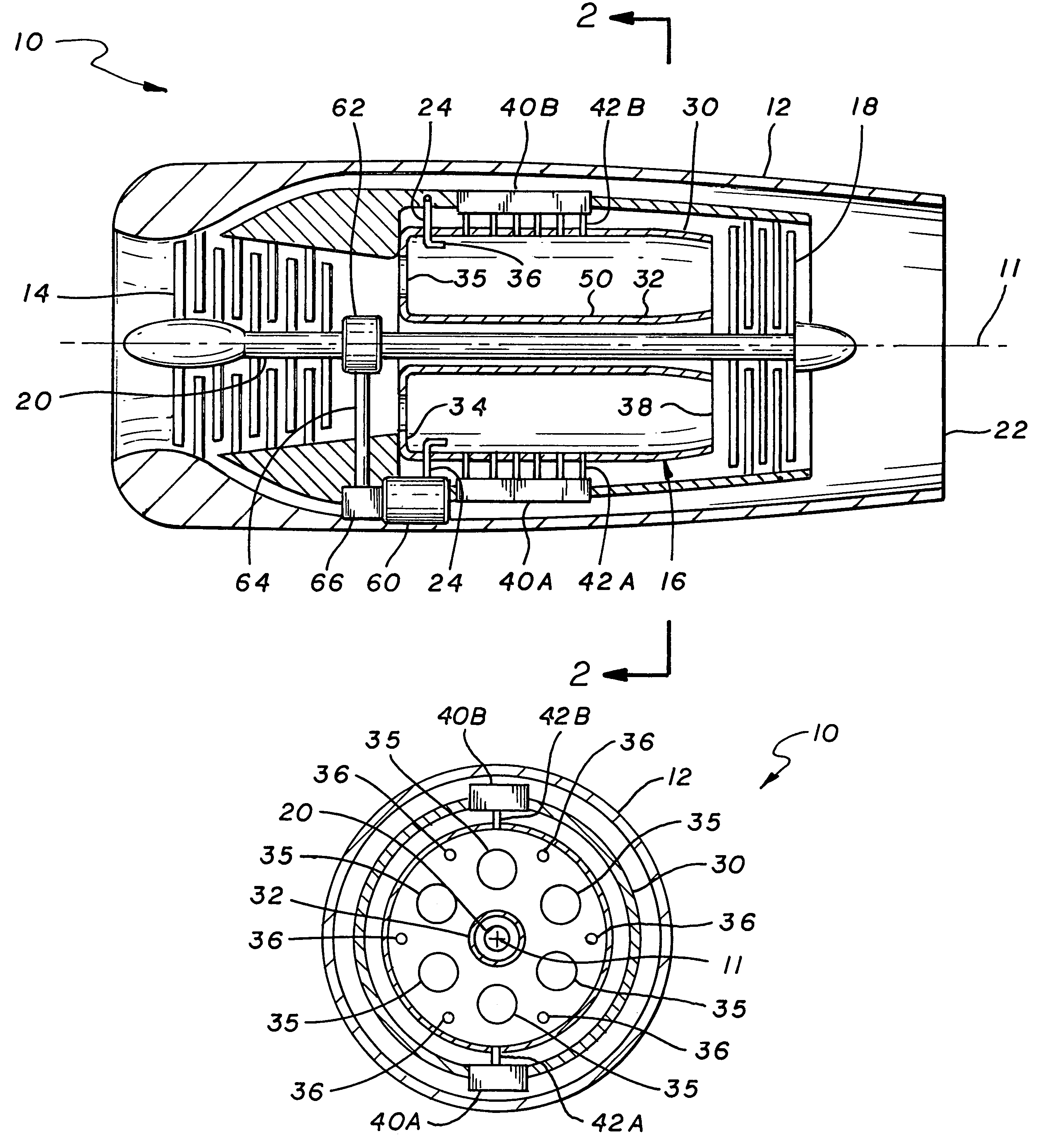
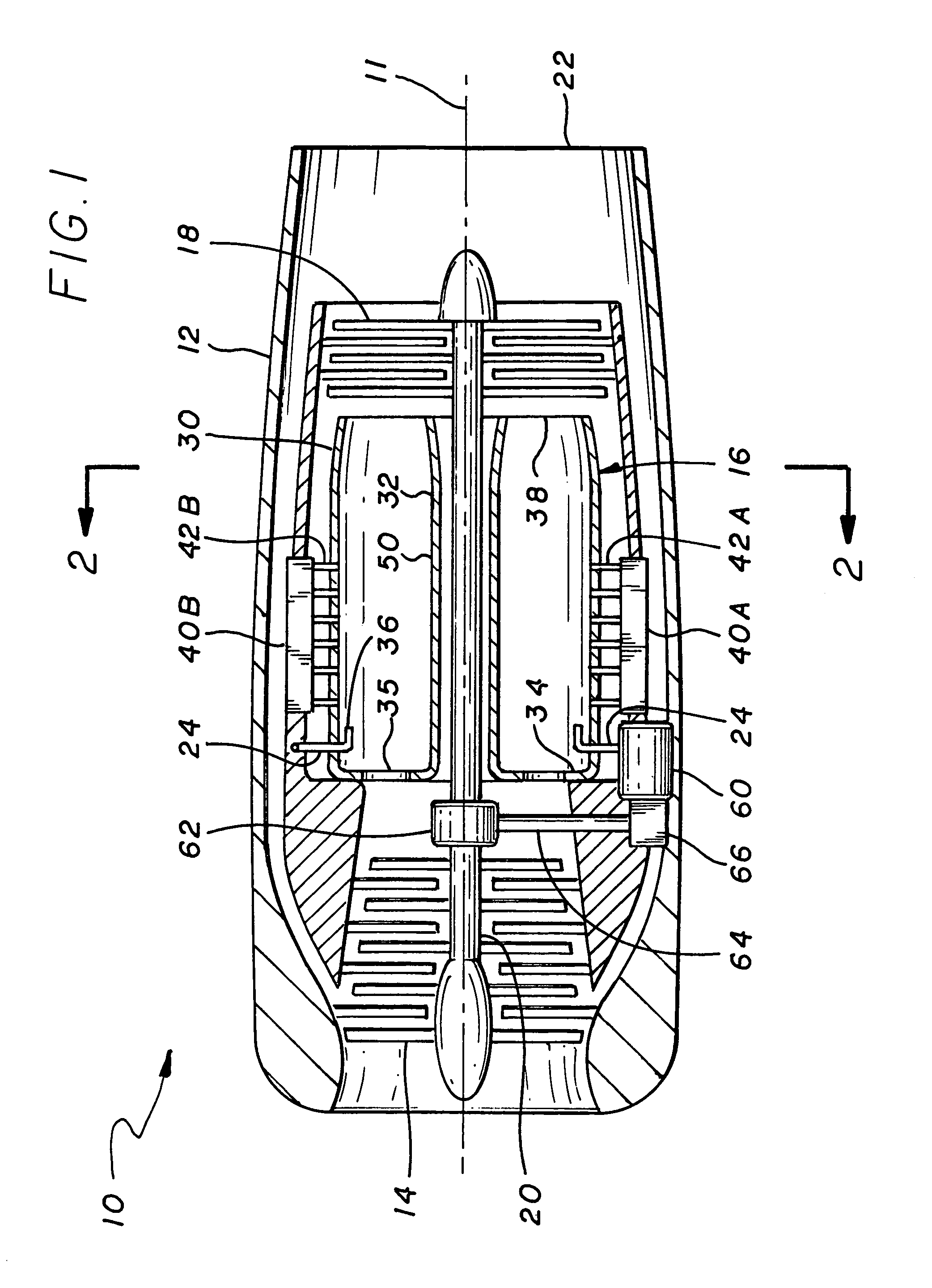
[0019]Referring to FIG. 1, the typical turbojet engine, generally indicated by numeral 10, having a longitudinal axis 11, The turbojet engine 10 includes a housing 12, compressor section 14 combustion section 16, turbine section 18 coupled by drive shaft 20 to the compressor, and an exhaust nozzle 22. Fuel is provided to the combustion section 16 by means a fuel system that includes fuel lines 24 coupled to a fuel pump (not shown). Air enters the compressor section 14, is compressed thereby; enters the combustion section where fuel is added and ignited and the hot gases pass through the turbine section 18 wherein energy is extracted to power the compressor section and thereafter exits out the exhaust nozzle 22. The combustion section 16 is ring shaped cylinder having an outer wall 30 and inner wall 32, a closed off front end 34 with compressed air inlet ports 35 and fuel injectors 36 and a nozzle end 38 for directing hot gas to the turbine section 18. While the above description is ...


PUM


Abstract

The invention is a turbojet propulsion system which includes a compressor section, a turbine section coupled by a shaft to the compressor section, a combustion section mounted between the compressor section and the turbine section, and an exhaust duct coupled to the aft end of said turbine section. A fuel delivery system is incorporated for supplying fuel to the combustion section. A laser assembly provides electromagnetic radiation to the combustion section. An electrical generator coupled to the turbine driven shaft powers the laser assembly.

Description

BACKGROUND OF THE INVENTION[0001]1. Field of the Invention[0002]The invention relates to the field of propulsion systems and, in particular, to a turbojet propulsion system wherein lasers are used to add additional energy to the combustion process.[0003]2. Description of Related Art[0004]Recent Defense Advanced Research Projects Agency (DARPA) advances in the field of Diode Pumped Solid State Laser Technology, specifically Fiber Lasers, have enabled scalable and robust system packaging architectures for operation in harsh environments. These next generation fiber laser systems require minimal thermal management and possess a relatively small footprint within an integrated assembly. The combination of a laser diode pump and an optical fiber gain medium makes possible extremely compact packages suitable for a diversity of applications. State of the art solid-state laser technology comprises three principal components, namely the lasing material (active medium), the optical pump source...

Claims


Application Information

Patent Timeline
Patent Type & Authority Patents(United States)
IPC IPC(8): F03H1/00G21D1/00H05B1/00
CPCF02C7/264F23C99/001F23R3/00Y02T50/671F23R2900/00006F23C2900/99003Y02T50/60
Inventor PAIS, SALVATORE
Owner NORTHROP GRUMMAN SYST CORP
Why Eureka
Try Eureka