Golf swing training device and training method

Inactive Publication Date: 2006-07-25
KALLASSY CHARLES A
13 Cites 14 Cited by

AI-Extracted Technical Summary

Problems solved by technology

However, despite these technologies, a golfer who lacks a proper repeatable golf swing is destined for inconsistency and frustration in the pursuit of golfing success and enjoyment.
Devices ...

Method used

[0041]A unique feature of the training method of the present invention is revealed by FIGS. 7A–E, which show the trainee separating his hands progressively during the backswing to a point of maximum separation at the top of the backswing and then progressively bringing the hands back into close proximity just prior to impact during the downswing. As seen best in FIGS. 7B and 7C, this training method enables the trainee to maintain his left arm in a substantially straight position during the backswing. It is well known that this is an important feature of an effective golf swing. By keeping a substantially straight left arm, the golfer can move the golf club through an arc that brings it back to its starting position at the point of impact to facilitate proper contact between the club face and the ball.
[0043]Another feature of the inventive training method is that the use of the slidable grip 20 promotes proper grip pressure with the right hand, both by virtue of the dynamic sliding motion and due to the contoured surfaces for the thumb, forefinger and second finger of the right hand. In other words, the third and fourth fingers of the right hand are slightly open resting against the back of the flair 24 so that they remain relaxed during the swing. The thumb, forefinger and second finger of the right hand apply pressure to the slidable grip 20, but the pressure is minimized due to the sliding action during the swing, during which the left hand properly applies most of the gripping pressure.
[0044]An alternative embodiment of the invention will now be described with reference to FIGS. 8–11. FIGS. 8 and 9 show a slidable grip designated generally by reference 100. The slidable grip 100 is designed for gripping by the right hand of a trainee as shown in FIGS. 10 and 11. As seen in FIG. 8, the slidable grip 100 has a hole 102, which is sized to permit a standard golf club handle, designated by 114 in FIG. 11, to be inserted through the opening 102. The slidable grip 100 preferably includes contoured surfaces for the thumb and first two fingers of the right hand. A hard durable ...

Benefits of technology

[0013]Another important object of the invention is to provide a method of training using the training device of the present invention repeatedly to imprint in the mind aspects of an effective golf swing. Yet another important object of the present invention is to provide a golf swing training device having a slidable grip for one hand that permits the hands, from any proximity, to separate progressively during the backswing and come back into proximity during the downswing and come back into proximity during the downswing prior to the point o...

Abstract

A slidable grip (20, 100, 200) for one hand is provided on the shaft (12, 312) of a modified golf club (10, 200, 300) to enable a golf trainee to separate his or her hands progressively during a backswing and being them back together progressively during the downswing. This technique imprints proper swing mechanics in the mind of the trainee to be recalled reflexively in executing a conventional golf swing with the hands in a fixed grip relationship on the handle (14, 114) of a golf club.

Application Domain

ClubsGolfing accessories +2

Technology Topic

EngineeringGolf club +2

Image

  • Golf swing training device and training method
  • Golf swing training device and training method
  • Golf swing training device and training method

Examples

  • Experimental program(1)

Example

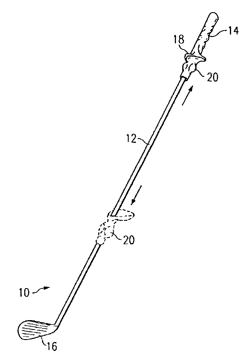
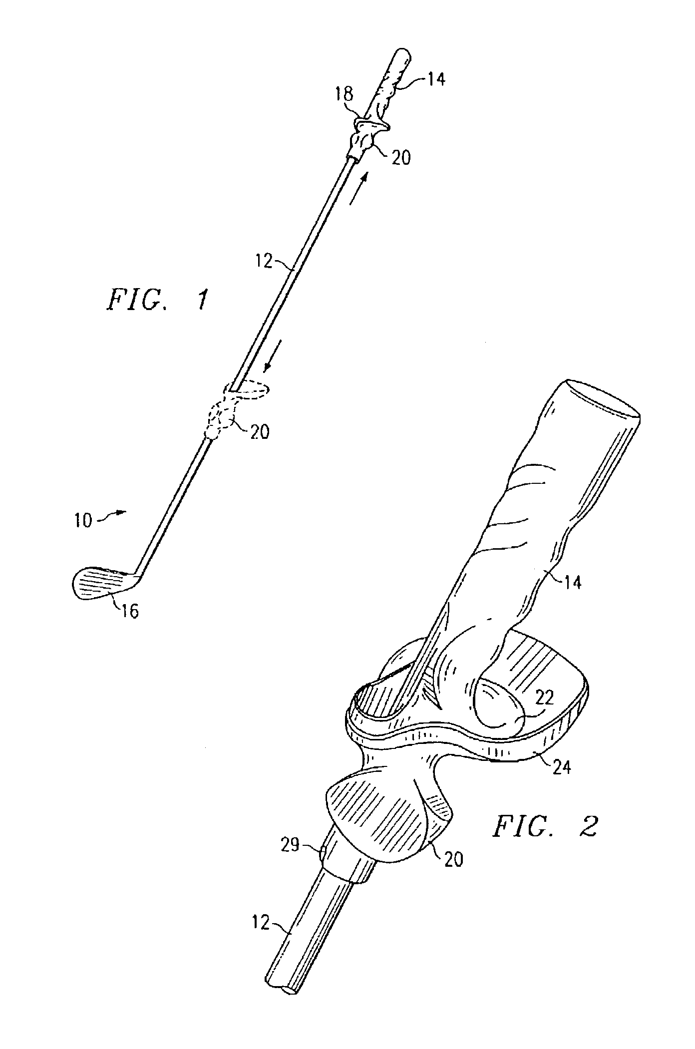
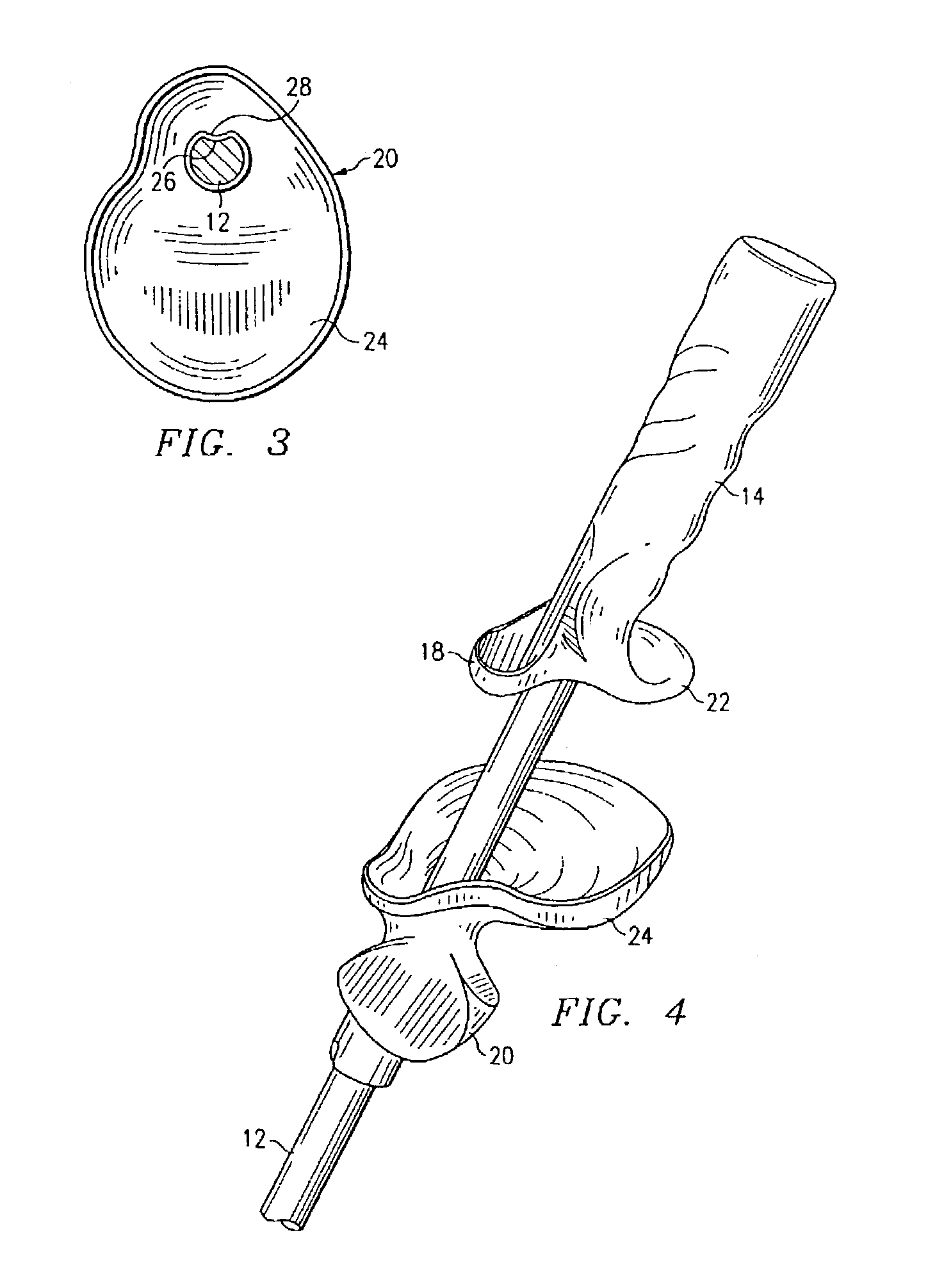
[0036]A preferred embodiment of the invention is illustrated in FIG. 1 and comprises a modified golf club 10. The golf club has an elongated shaft 12 with a handle 14 at one end and a conventional head 16 at the other end. Alternatively, the conventional head 16 can be replaced by a weight or other nonconventional termination. The golf club 10 shown is a right-handed golf club, but it will be appreciated that the invention applies equally to a left-handed golf club, for which appropriate modifications can be made as will become apparent from the following description. The handle 14 is fixed to the end of the golf club 10 and preferably includes a grip having contoured surface conforming, and correctly positioning and aligning, to the thumb and forefinger of the user's left hand. Additional contoured surfaces can be added to conform to additional fingers of the left hand. The grip 18 and handle 14 are preferably integrally formed as a molded unit using an suitable material or combination of materials, preferably using hard rubber or durable plastic.
[0037]In accordance with an important feature of the present invention, the device 10 includes a slidable right-hand grip 20, which is shown in two positions with the arrows designating the sliding movement along the shaft 12. The slidable grip 20 is shown in full lines in mating contact with the fixed grip 18 and in phantom lines spaced slightly more than halfway down the shaft. As shown in the enlarged view of FIG. 2, the slidable grip 20 preferably has contoured surfaces that conform to, and correctly position and align, the thumb and fingers of the right hand of the user. The grips 18 and 20 have mating services defined by outwardly extending flairs 22 and 24. FIG. 3 shows the top surface of flair 24, which is part of the slidable grip 20.
[0038]Also shown in FIG. 3 is an optional modification that maintains alignment of the grip 20 with the shaft 12 during sliding movement of the grip along the shaft. The shaft 12 may include a groove 26 extending longitudinally along its length at least along the portion that accommodates sliding movement of the grip 20. Correspondingly, the grip 20 has a tongue 28 that extends into the groove 26 so that the grip 20 will not rotate with respect to the shaft 12 during sliding movement.
[0039]Referring to FIGS. 4 and 5, the slidable grip 20 is shown slightly separated from the fixed grip 18. The flairs 22 and 24 perform multiple functions. First, they provide mating surfaces that keep the slidable grip 20 in proper orientation with respect to the fixed grip when the slidable grip 20 is in abutting contact with the fixed grip 18. Second, the outwardly flared portions 22 and 24 protect the fingers and hands of the user from being pinched when the slidable grip 20 is brought quickly into contact with the fixed grip 18. Third, when the flairs 22 and 24 come back into contact during the downswing, they make a snapping sound at the simulated moment of impact to trigger desired wrist-roll action during followthrough. When the slidable grip 20 is in abutting contact with the fixed grip 18, the hands of the user will be properly positioned in a standard golf grip by employing the contoured surfaces to position the thumbs and fingers of the hands. Additional features of the contoured gripping surfaces of the fixed grip 18 and the slidable grip 20 are revealed in FIGS. 6A, 6B and 6C. In particular, as illustrated best in FIG. 6A, the slidable grip 20 preferably has an alignment notch 29 that squares the slidable grip 20 at the top of the backswing when the slidable grip engages the clubhead 16 with the notch 26 mating with the upper edge of the clubhead.
[0040]Important additional features of the invention will now be described in connection with FIGS. 7A–E showing the golf swing training device 10 at several positions during a training swing. FIG. 7A shows a trainee at the address position with his left hand grasping the fixed grip and his right hand grasping the slidable grip. In FIG. 7B the trainee has begun the backswing and has started to separate his hands by pushing the slidable grip part way down the shaft 12. FIG. 7C shows the trainee having reached the top of the backswing in a fully coiled position with a substantially straight left arm and the right hand extending to almost the remote end of the shaft. FIG. 7D shows the trainee at a point in the swing just prior to impact in which the hands have been pulled back into close proximity with the slidable grip and fixed grip in mating contact. When the two grips are brought into mating contact, the hands are returned to the proper grip orientation and alignment relative to the handle of the golf club training device 10. FIG. 7E shows the trainee at a point in the golf swing after impact and part way through the followthrough with the hands still in close proximity at the handle of the golf swing training device 10.
[0041]A unique feature of the training method of the present invention is revealed by FIGS. 7A–E, which show the trainee separating his hands progressively during the backswing to a point of maximum separation at the top of the backswing and then progressively bringing the hands back into close proximity just prior to impact during the downswing. As seen best in FIGS. 7B and 7C, this training method enables the trainee to maintain his left arm in a substantially straight position during the backswing. It is well known that this is an important feature of an effective golf swing. By keeping a substantially straight left arm, the golfer can move the golf club through an arc that brings it back to its starting position at the point of impact to facilitate proper contact between the club face and the ball.
[0042]Another feature of the unique training method seen best in FIGS. 7B and 7C is the ability to separate the hands during the backswing. This enables the trainee to stretch and make a full shoulder turn without bending the left arm. This separation and slide of the hands from proximity during the backswing and subsequent return to proximity during the downswing teaches the proper rhythm and tempo of a golf swing in addition to teaching the proper inside out swing path of the golf club during the downswing. By repeatedly practicing the hand separation and return technique of the inventive method, the trainee can learn or imprint in muscle memory these important aspects of an effective golf swing. When the trainee then uses a conventional golf club and keeps his or her hands together on the handle at all times during the swing, the natural tension between the straight left arm position and the full shoulder turn position will compromise to produce a mechanically effective and technically correct golf swing motion.
[0043]Another feature of the inventive training method is that the use of the slidable grip 20 promotes proper grip pressure with the right hand, both by virtue of the dynamic sliding motion and due to the contoured surfaces for the thumb, forefinger and second finger of the right hand. In other words, the third and fourth fingers of the right hand are slightly open resting against the back of the flair 24 so that they remain relaxed during the swing. The thumb, forefinger and second finger of the right hand apply pressure to the slidable grip 20, but the pressure is minimized due to the sliding action during the swing, during which the left hand properly applies most of the gripping pressure.
[0044]An alternative embodiment of the invention will now be described with reference to FIGS. 8–11. FIGS. 8 and 9 show a slidable grip designated generally by reference 100. The slidable grip 100 is designed for gripping by the right hand of a trainee as shown in FIGS. 10 and 11. As seen in FIG. 8, the slidable grip 100 has a hole 102, which is sized to permit a standard golf club handle, designated by 114 in FIG. 11, to be inserted through the opening 102. The slidable grip 100 preferably includes contoured surfaces for the thumb and first two fingers of the right hand. A hard durable plastic, rubber or combinations thereof, are suitable materials for the grip 100. The contoured surfaces include a thumb socket 104, an index finger socket 106, and a second finger socket 108. These sockets are arranged to teach proper positioning of the thumb and first two fingers of the right hand, and to teach the trainee to provide moderate grip pressure with the thumb and first two fingers of the right hand and essentially no pressure with the third and fourth fingers of the right hand. It is well known that the left hand of a right-handed golfer needs to be the dominant hand in preforming a golf swing. Thus, the present invention facilitates training a golfer in the mechanics of proper grip pressure and facilitates the method of use as taught herein. The alternative embodiment 100 of FIGS. 8–11 can be used to execute a training swing similar to that shown in FIGS. 7A–E. As a further alternative that is effective in teaching swing mechanics, grip 100 can be modified in the form of a cylinder without the contoured surfaces for the fingers. This alternative can provide a slidable grip without having to customize its outer surfaces to fit various hand sizes, yet can facilitate to a degree the method of use described herein.
[0045]Now referring to FIGS. 12 and 13, another alternative embodiment of the present invention, which is designated generally by reference numeral 200, will be described. The golf swing training device 200 is similar to the device 10 of FIG. 1 with the addition of a stop ring 202. The stop ring 202 is shown in full lines abutting a slidable grip 220 and in phantom lines at two different positions along the shaft 12. The stop ring 202 preferably includes a contoured upper surface that mates in one rotational orientation with a lower rotating surface of the slidable grip 220. This causes the trainee to properly position his right hand as shown in FIG. 13 so that club head 16 is properly oriented at the top of the backswing. Slidable grip 220 in other respects is like the slidable grip 20 previously described.
[0046]The stop ring 202 may be positioned at any location along the shaft 12 between the upper end as shown in full lines in FIG. 12 and the remote end near the head 16. The stop ring 202 has suitable means for securing it in position along the shaft 12 such as by means of a clamp (not shown) or other frictional engagement means. Such a clamp can be provided within an outwardly flared collar 204. Alternatively, a conventional set-screw (not shown) or other such means can be used to secure the stop ring 202 at a selected position along the shaft 12.
[0047]FIG. 13 shows the stop ring 202 in use during a training swing. By securing the stop ring 202 in the position shown, the trainee has the sliding motion of his right hand restricted. FIG. 13 shows the trainee executing a golf swing arriving at the top of the backswing with the slidable grip 220 abutting the stop ring 202. During the course of training, the stop ring 202 is moved progressively up the shaft at spaced intervals until it finally is positioned all the way up the shaft as shown in full lines in FIG. 12. Thus, for example, each day the stop ring 202 can be moved several inches up the shaft 12 so that the trainee progressively brings his or her hands closer together until they are adjacent to each other as in a conventional golf swing. Additionally, when the slidable grip 220 is in abutment with the stop ring 202 the golfer can pause in such position as shown in FIG. 13 and by a pushing motion of the slidable grip 220 against stop ring 202 can effect a stretching motion on the body of the golfer thereby causing the golfer to stretch the appropriate muscles of the body that are involved in the maximum “coiling” of the body. Upon “release” of this coiling there is effected the maximum clubhead speed during the downswing and follow-through of the golf swing. Thus, the results of this stretching and the muscle memory of these positions are retained in the “muscle memory” of the golfer and can then be executed by the golfer with a conventional golf club.
[0048]Now referring to FIGS. 14 and 15, another alternative embodiment generally designated by reference numeral 300 will be described. For occasions when the trainee would like to practice the training method in a confined space (i.e., indoors) the alternative swing training device 300 has a shortened shaft 312, which is preferably a maximum of 24 inches from end to end. In order to give the training device 300 the feel of a conventional golf club, a weight 330 is provided on the shaft 312. The weight 330 is preferably slidable along the shaft 312 and includes means for locking it at selected positions along the shaft, a first position being shown in full lines and a second position being shown in phantom lines. By locating the weight at different positions along the shaft, the angular momentum of different clubs from driver to wedge can be simulated.
[0049]Referring specifically to FIG. 15, the weight 330 has a set-screw 332 or similar locking means that can be used to secure the weight 330 at a selected position along the shaft 312 by tightening the set-screw 332 against the shaft 312. An additional feature of the weight 330 that can be included is a contoured upper portion 334 that includes a projection 336. The upper portion can be rubber or molded plastic and can be glued or otherwise joined to a main body portion 338 along an interface 340. The main body 338 of the weight 330 is preferably metal. Referring again to FIG. 14, the projection 336 is shaped to mate with the match 29 at the lower end of a slidable grip 20. This serves a similar purpose as the mating of the slidable grip 220 and the stop ring 202 as described above with reference to FIG. 13. Alternatively, weight 330 can be fixed at the remote end of a stop ring like that shown in FIGS. 12 and 13 can be employed.
[0050]From the foregoing, it will be appreciated that the present invention provides a unique swing training device and method for its use in training a golfer to execute an effective golf swing. The present invention contemplates that similar concepts can have application for training in other sports. For example, a slidable grip could be used effectively with a baseball swing training device generally similar to a conventional baseball bat. Although the invention has been described with reference to several preferred and alternative embodiments, it will be understood by those skilled in the art having reference to the current specification and drawings, that various modifications may be made and further alternatives are possible without departing from the spirit and scope of the invention as set forth in the appended claims.

PUM

no PUM

Description & Claims & Application Information

We can also present the details of the Description, Claims and Application information to help users get a comprehensive understanding of the technical details of the patent, such as background art, summary of invention, brief description of drawings, description of embodiments, and other original content. On the other hand, users can also determine the specific scope of protection of the technology through the list of claims; as well as understand the changes in the life cycle of the technology with the presentation of the patent timeline. Login to view more.
Why Eureka
Try Eureka