Instrumentation and method for delivering an implant into a vertebral space
What is Al technical title?
Al technical title is built by PatSnap Al team. It summarizes the technical point description of the patent document.
a technology of vertebral space and instrumentation, applied in the field of surgical instruments and methods for treating the spine, can solve the problems of low leg pain, loss of muscle control or paralysis, weakened annulus fibrosis and/or other portions of the intervertebral disc, etc., and achieve the effect of improving instrumentation and methods
Inactive Publication Date: 2006-07-25
WARSAW ORTHOPEDIC INC
View PDF13 Cites 317 Cited by
Summary
Abstract
Description
Claims
Application Information
AI Technical Summary
This helps you quickly interpret patents by identifying the three key elements:
Problems solved by technology
Method used
Benefits of technology
[0015]It is one object of the present invention to provide improved instrumentation and methods for delivering an implant into a vertebral space.
Problems solved by technology
A herniated disc may bulge out and compress itself onto a nerve, thereby resulting in lower leg pain, loss of muscle control or paralysis.
A degenerative disc disease typically causes the intervertebral disc to gradually reduce in height, thereby causing the annulus fibrosus to buckle, tear or separate in a radial and / or circumferential direction, commonly resulting in persistent and disabling back pain.
One drawback of current prosthetic disc implants is that the annulus fibrosis and / or other portions of the intervertebral disc are weakened by either large or multiple incisions and / or cut outs that are required in order to insert the prosthetic disc implant into the intervertebral space between adjacent vertebrae.
Additionally, incisions or cut outs in the annulus fibrosis are not easily repaired, thereby increasing the risk that the prosthetic disc implant may eventually work its way out of the intervertebral space and possibly interfere with or damage adjacent anatomical tissue.
A further deficiency of current prosthetic disc implants is that multiple laterally spaced prosthetic implants are sometimes required to be inserted within the intervertebral space, thereby requiring careful and precise positioning of the prosthetic implants to ensure proper load carrying characteristics.
Method used
Image
Click on the blue label to locate the original text in one second.
Reading with bidirectional positioning of images and text.
Examples
Embodiment Construction
[0041]For the purposes of promoting an understanding of the principles of the invention, reference will now be made to the embodiments illustrated in the drawings and specific language will be used to describe the same. It will nevertheless be understood that no limitation of the scope of the invention is hereby intended, such alterations and further modifications in the illustrated devices, and such further applications of the principles of the invention as illustrated herein being contemplated as would normally occur to one skilled in the art to which the invention relates.
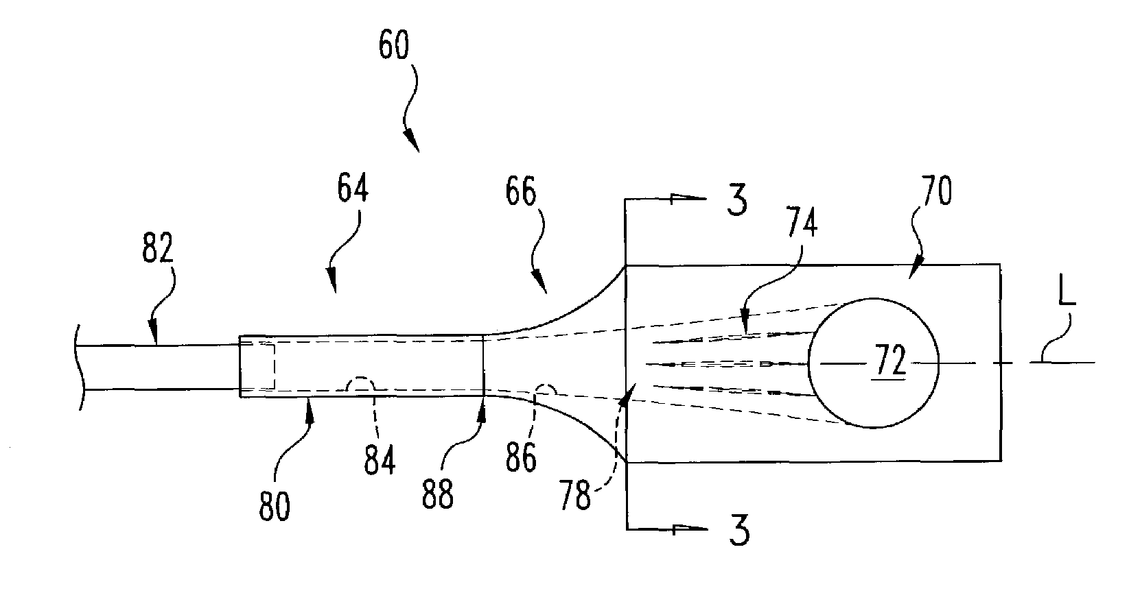
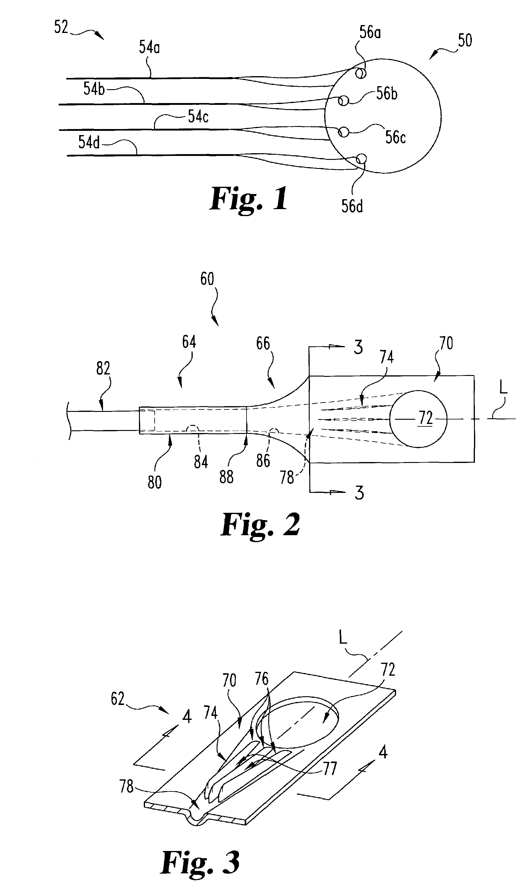
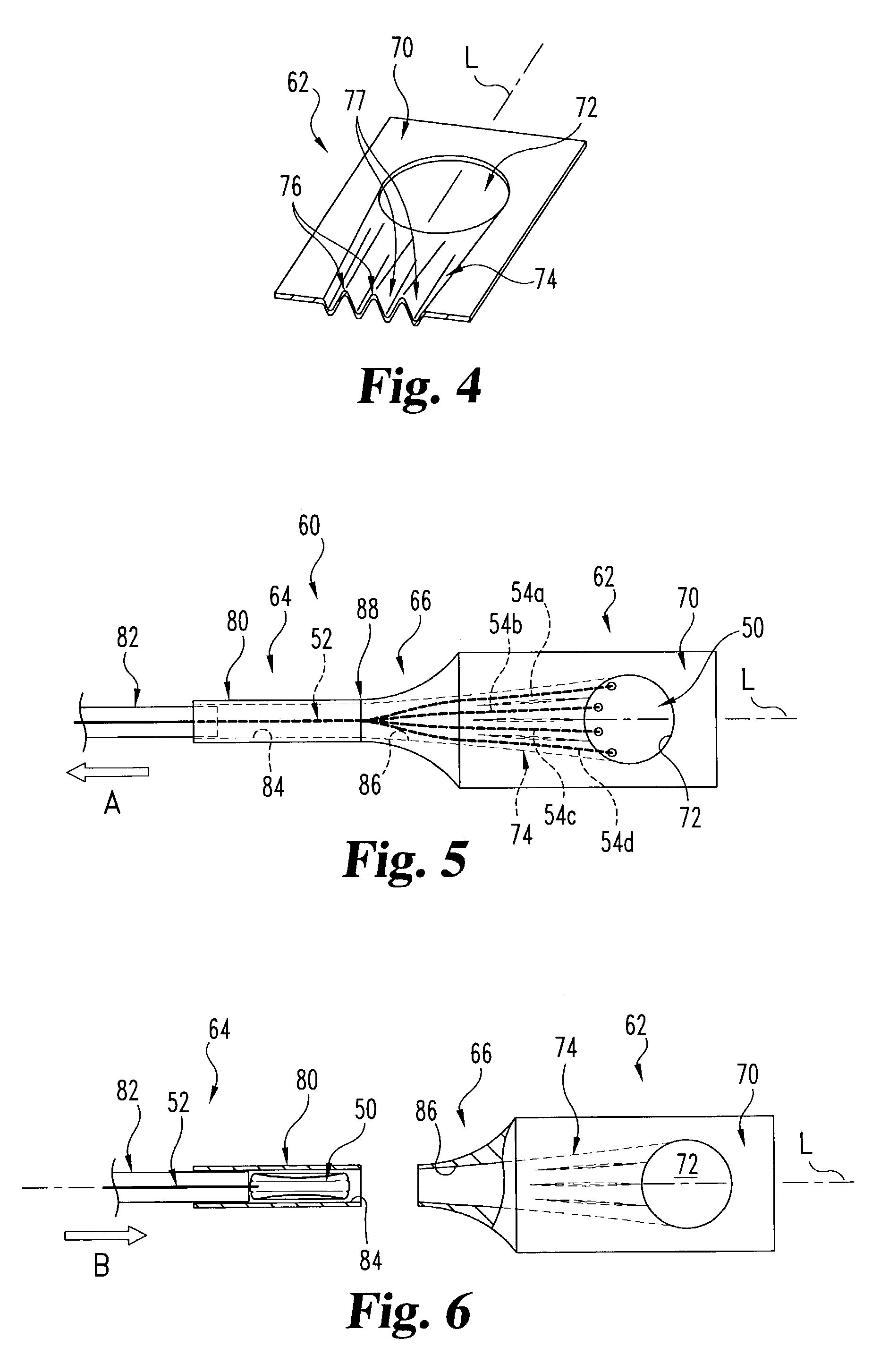
[0042]Referring to FIG. 1, shown therein is an implant 50 according to one form of the present invention. In one embodiment of the invention, the implant 50 is a spinal implant suitable for insertion into a vertebral space. In a specific embodiment, the implant 50 is a prosthetic nucleus suitable for insertion into an intervertebral disc space to replace at least a portion of the nucleus pulposus of a natural in...
PUM
Property
Measurement
Unit
relative displacement
aaaaa
aaaaa
transverse dimension sized
aaaaa
aaaaa
transverse dimension
aaaaa
aaaaa
Abstract
Instrumentation and method for delivering an implant into an intervertebral disc space, including a die member configured to transition the implant from an initial configuration to a deformed configuration having a reduced lateral profile suitable for insertion into the intervertebral disc space in a minimally invasive manner. In one embodiment, the die member includes an opening sized to receive the implant while in the initial configuration, and wherein relative displacement between the implant and the die member causes the implant to transition toward the reduced-profile deformed configuration. In a specific embodiment, the opening comprises an axial passage including a first portion having a rectangular cross-section corresponding to a substantially planar initial configuration of the implant, and a second portion having a circular cross-section corresponding to a substantially cylindrical deformed configuration of the implant.
Description
CROSS REFERENCE TO RELATED APPLICATIONS[0001]The present application claims the benefit of now abandoned U.S. Provisional Application Ser. No. 60 / 341,343, filed Dec. 13, 2001, and is a continuation-in-part application of U.S. patent application Ser. No. 09 / 998,978, filed Nov. 15, 2001, now U.S. Pat. No. 6,733,505, which claims the benefit of U.S. Provisional Application Ser. No. 60 / 248,807, filed Nov. 15, 2000, and is also a continuation-in-part application of U.S. patent application Ser. No. 09 / 559,899, filed Apr. 26, 2000, now U.S. Pat. No. 6,764,514, which claims the benefit of U.S. Provisional Application Ser. No. 60 / 131,053, filed Apr. 26, 1999, the contents of each application hereby being incorporated by reference in their entirety.FIELD OF THE INVENTION[0002]The present invention relates generally to the field of surgical instrumentation and methods for treatment of the spine, and more particularly relates to instrumentation and methods for delivering an implant into a verte...
Claims
Application Information
Patent Timeline
Application Date:The date an application was filed.
Publication Date:The date a patent or application was officially published.
First Publication Date:The earliest publication date of a patent with the same application number.
Issue Date:Publication date of the patent grant document.
PCT Entry Date:The Entry date of PCT National Phase.
Estimated Expiry Date:The statutory expiry date of a patent right according to the Patent Law, and it is the longest term of protection that the patent right can achieve without the termination of the patent right due to other reasons(Term extension factor has been taken into account ).
Invalid Date:Actual expiry date is based on effective date or publication date of legal transaction data of invalid patent.