Process for sensor resources management

a sensor resource and processing technology, applied in the field of sensor resource management and tracking fusion, can solve the problems of difficult tracking of vehicles on the ground by radar from aircraft, and unclear identity of vehicles for tracking purposes, so as to maximize the performance of the radar system and optimize the ability of the radar system to track vehicles

Active Publication Date: 2006-07-25
NORTHROP GRUMMAN SYST CORP
View PDF20 Cites 30 Cited by
  • Summary
  • Abstract
  • Description
  • Claims
  • Application Information

AI Technical Summary

Benefits of technology

[0008]Tracking vehicles on the ground by radar from an aircraft can be difficult. First of all, there may be a multiple number of vehicles in the immediate area, with several nominated for tracking. In addition, the vehicles may cross paths with other nominated or non-nominated vehicles, or become so close to each other that their identity for tracking purposes may be come ambiguous. Thus maximizing the performance of the radar systems becomes paramount. The radar systems, which are steered array type, can typically operate in three modes:1. Moving target Indicator (MTI) mode. In this mode, the radar system can provide good kinematic tracking data.2. High range resolution (HRR) mode. In this mode, the radar system is capable of providing target profiles.3. High update rate (HUR) mode. In this mode, target is tracked at very high rate, such that the position is accurately determined.Tracking performance is enhanced if the radar is operated in the mode best suited to type of information required.
[0013]If there are two aircraft monitoring the area, then the second aircraft will take the second highest score with the limitation that the radar operates in a different mode to eliminate interference between the radar systems.

Problems solved by technology

Tracking vehicles on the ground by radar from an aircraft can be difficult.
In addition, the vehicles may cross paths with other nominated or non-nominated vehicles, or become so close to each other that their identity for tracking purposes may be come ambiguous.

Method used


Image

  • Process for sensor resources management
  • Process for sensor resources management
  • Process for sensor resources management

Examples


Embodiment Construction

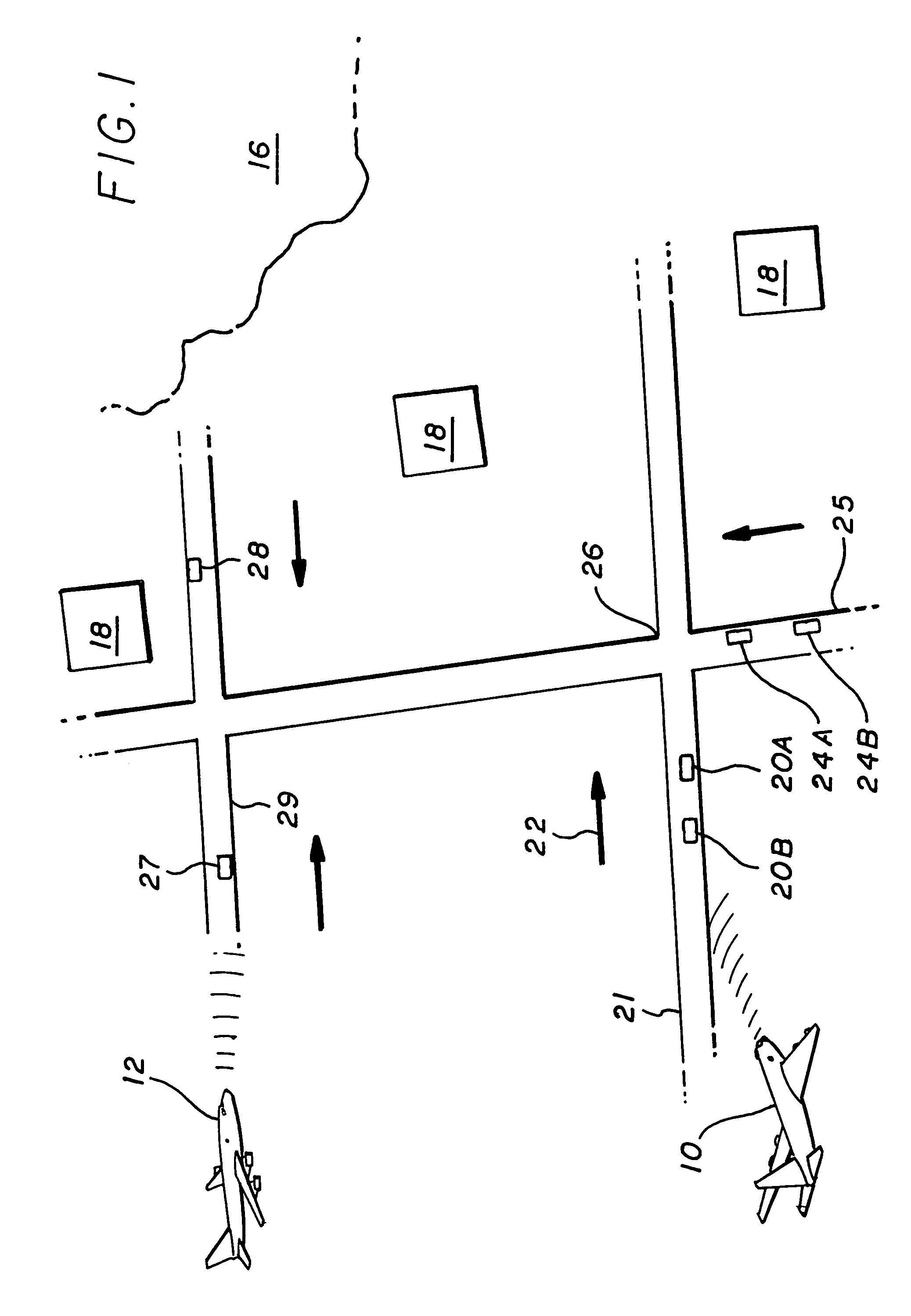
[0064]Referring to FIG. 1, which is a simplified view of terrain wherein several vehicles are traveling and are being monitored by aircraft 10 and 12. Because the vehicle position as well as its velocity and direction of travel are estimates, they are generally defined as “tracks”, thus vehicle and track are used interchangeably hereinafter. The terrain includes hills 16, with several structures 18 nearby. Vehicles 20A, and 20B are traveling on road 21 in the direction indicated by arrow 22 toward the hills 16. Vehicles 24A, and 24B are traveling on road 25, which intersects road 21 at point 26, while vehicle 27 and 28 are traveling toward each other on road 29 some distance away. The situation illustrated in FIG. 1 is for purposes of illustration, for any real situation in the battlefield will be far more complex. Furthermore, while two aircraft are shown, there may be only one or more than two aircraft involved in the tracking. In addition, while aircraft are used, the system coul...


PUM


Abstract

The subject process accepts the data from a kinematic tracker and maps them to fuzzy set conditions. Then using a multitude of defined membership functions and fuzzy logic gates, generates sensor mode control rules. It does this for every track and each sensor. The Rule with the best score becomes a sensor cue, which is used to place the sensor into one of three operating modes. If there are ambiguities do to one or more vehicles coming in to close proximity to each other process compares radar profiles of vehicle to those stored in an “on the fly” data base to eliminate the ambiguities.

Description

BACKGROUND OF THE INVENTION[0001]1. Field of the Invention[0002]The invention relates to the field of sensor resources management and tracking fusion and, in particular, to the management and data fusion of sensors such as radar systems used to detect and monitor moving targets.[0003]2. Description of Related Art[0004]Tracking moving ground targets by radar from an aircraft in a battlefield situation is a difficult process. First of all, there may be a large number of moving vehicles in the vicinity of the targets of interest. In addition, the terrain and foliage can intermittently block surveillance. Thus sensor management is critical. In most previous tracking instances, the tracker was data driven. Trackers were at the mercy of the data they ingested. The only way to improve performance was to fine tune prediction models, sensor models, and association algorithms. Such fine-tuning led to improved performance, but only marginally. Potentially, trackers could realize much more sign...

Claims


Application Information

Patent Timeline
Patent Type & Authority Patents(United States)
IPC IPC(8): G01S13/52
CPCG01S13/726
Inventor COLLINS, NOELMOORE, KIRK D.MCMILLAN, DONALD R.
Owner NORTHROP GRUMMAN SYST CORP
Why Eureka
Try Eureka