
Palm print scanner and methods

a palm print and scanner technology, applied in the field of biometrics, can solve the problems of palm natural curve, loss of biometric information, and dead spot at the palm pocket, and achieve the effect of substantially eliminating dead spots and eliminating dead spots

Active Publication Date: 2006-07-25
HID GLOBAL CORP
View PDF108 Cites 26 Cited by
  • Summary
  • Abstract
  • Description
  • Claims
  • Application Information

AI Technical Summary

Benefits of technology

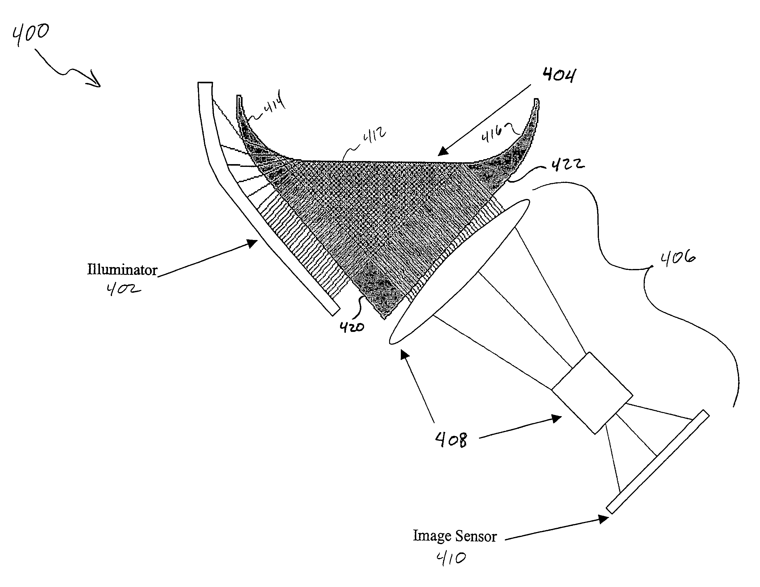
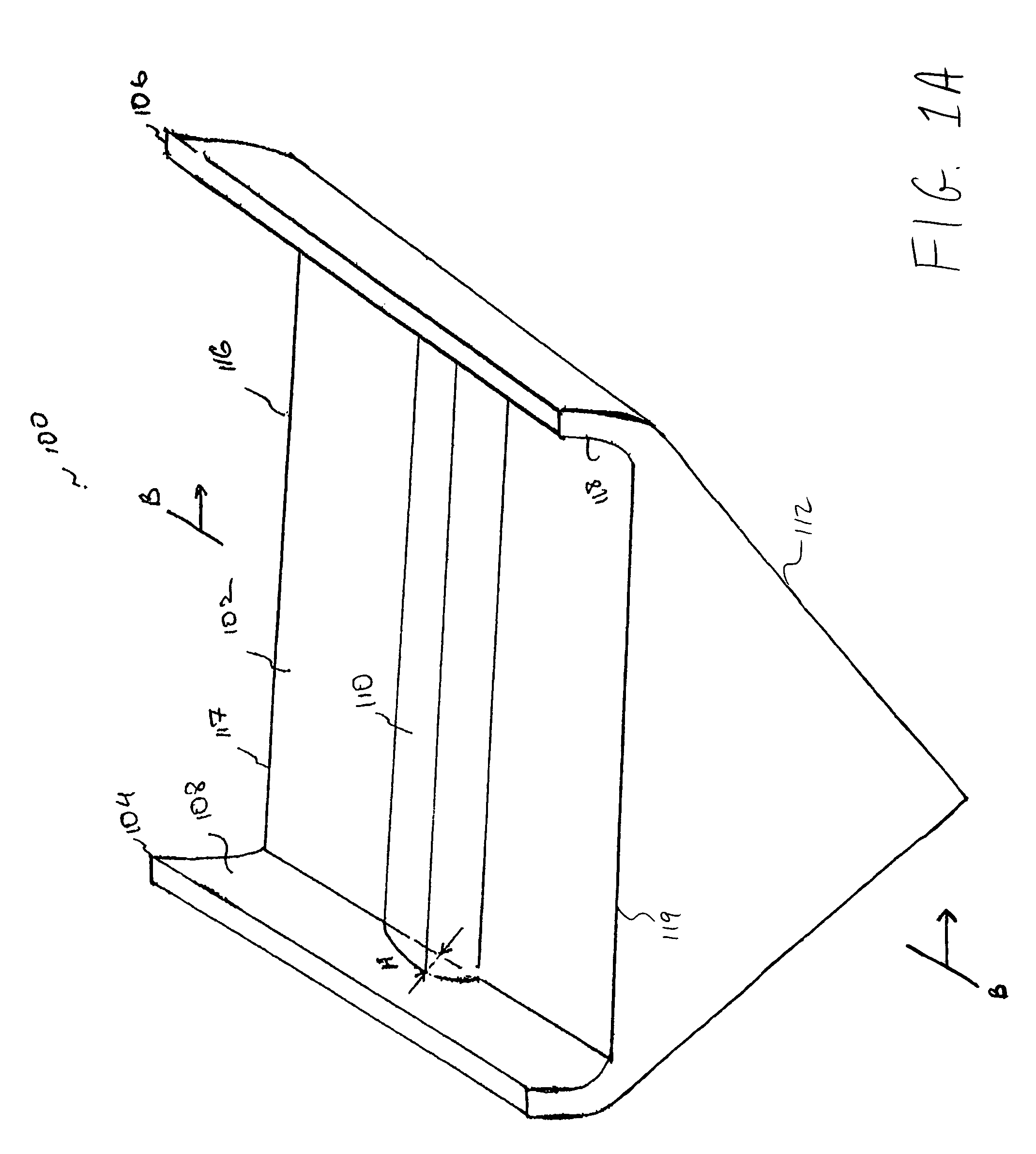
The present invention provides a system and method for live palm print scanning. The system includes a transparent tray platen apparatus and a scanning assembly. The tray platen apparatus has a base region and two side regions that form a scanning surface. The scanning assembly moves along the outside surface of the tray platen apparatus to capture the complete palm print pattern. The system can also capture both hands of an individual sequentially or simultaneously. The technical effect of the invention is the elimination of the "dead spot" and the ability to capture a complete image of the palm print pattern and side edges of the palm in a single scan.

Problems solved by technology

One problem with conventional palm live scanner systems is that a palm naturally curves, while a typical platen has a flat planar surface upon which a palm is placed.
If this occurs, a “dead spot” can occur at the palm pocket and biometric information can be lost.
Another problem is the difficulty in capturing an image of a print pattern on the outer edge of the palm located opposite the thumb (also called the writer's palm).
As a result, the print pattern on the side of the palm including the writer's palm can only be captured in a separate scan from the scan of the main palm itself.
Two scans is expensive, more complex, and burdensome to palm print scanner users.
Such attempts, however, do not overcome the above-mentioned problems.

Method used


Image

  • Palm print scanner and methods
  • Palm print scanner and methods
  • Palm print scanner and methods

Examples


Embodiment Construction

[0033]While specific configurations and arrangements are discussed, it should be understood that this is done for illustrative purposes only. A person skilled in the pertinent art will recognize that other configurations and arrangements can be used without departing from the spirit and scope of the present invention. It will be apparent to a person skilled in the pertinent art that this invention can also be employed in a variety of other applications.

[0034]FIGS. 3A and 3B illustrate different sections of a user's palm that can be imaged with the present invention. FIG. 3A illustrates various sections of an inner surface of a palm 300. Palm pocket 302 is located in the center of palm 300. Hypothenar region 304 is located on the portion of the palm opposite the thumb. FIG. 3B illustrates a writer's palm 306 on palm 300. Writer's palm 306 is part of hypothenar region 304, and refers to the area which, for example, normally rests against paper when the user is writing. Writer's palm 3...


PUM


Abstract

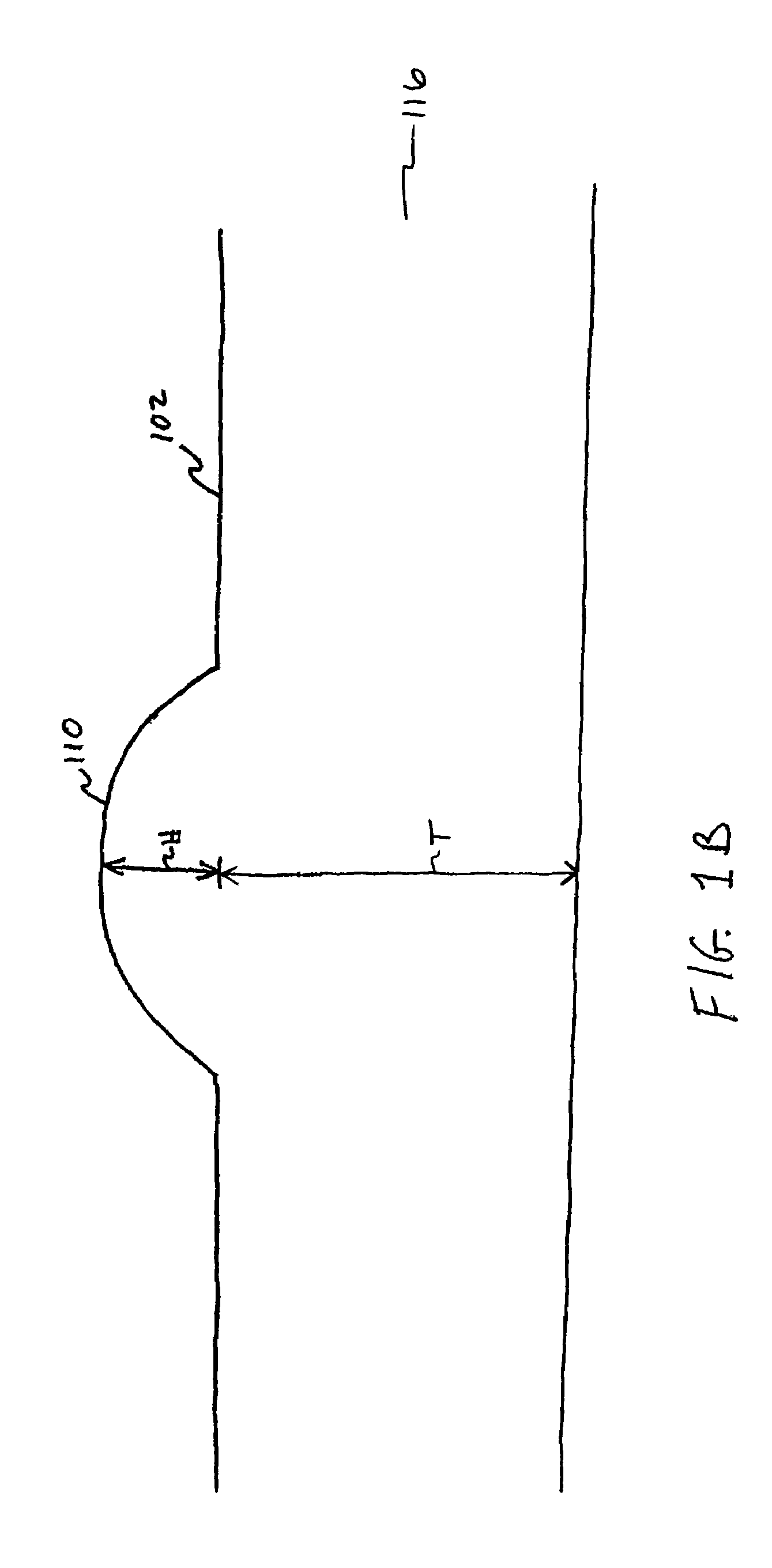
A live print scanner includes a transparent tray platen apparatus and a scanning system. The transparent tray platen apparatus includes a base region attached to two rounded side regions. The base region of the tray platen assembly includes a convex portion. A hand is placed atop the base region adjacent to one of the two rounded side regions such that the hand's palm pocket is atop the convex portion. A sensor assembly within the rotary scanning system generates a complete image of a palm print pattern. Because of the side regions and the convex portion, the image generated includes an image of a print pattern on the palm pocket as well as on the side of the palm. A holographic element may be disposed in a light path between an illumination source and the sensor.

Description

CROSS REFERENCE TO RELATED APPLICATIONS[0001]This application claims the benefit of U.S. Provisional Application No. 60 / 509,541, filed Oct. 9, 2003, hereby incorporated by reference herein in its entirety.BACKGROUND OF THE INVENTION[0002]1. Field of the Invention[0003]The present invention relates to the field of biometrics. More specifically, the present invention relates to live scanning of prints.[0004]2. Background Art[0005]Print imaging systems can capture images of prints on thumbs, fingers, palms, toes, feet, and / or hands. Such print imaging systems are also referred to as live scanners, live print scanners, or simply scanners. Live scanners often include a light source, platen and camera. An object having a print pattern is placed on the platen. A platen is often one planar surface of a prism. The light source illuminates the platen. The camera captures an image of a print placed on the platen.[0006]Many live print scanners utilize the optical principle of frustrated total i...

Claims


Application Information

Patent Timeline
Patent Type & Authority Patents(United States)
IPC IPC(8): G06K9/74G06K
CPCG06K9/00046G06V40/1324
Inventor CARVER, JOHN F.MCCLURG, GEORGE W.
Owner HID GLOBAL CORP
Learn More