Optical module with latching/delatching mechanism

a technology of optical modules and latching mechanisms, applied in the direction of optical elements, coupling device connections, instruments, etc., can solve the problems of incompatibility of transceiver manufacturers, inability to accurately fit the mounting cage of modules, and inability to meet the requirements of network devices

Active Publication Date: 2006-08-01
SUMITOMO ELECTRIC DEVICE INNOVATIONS U S A
View PDF3 Cites 38 Cited by
  • Summary
  • Abstract
  • Description
  • Claims
  • Application Information

AI Technical Summary

Problems solved by technology

Yet, while the availability of competing products may be useful this availability has led to a lack of device uniformity.
A network designer is cautious when selecting an optical module, because modules may or may not accurately fit the network device's mounting cage, depending on the relative dimensions of the two.
As a result, transceiver manufactures still run the risk of producing equipment incompatible with a particular network device.
Improperly fitting modules also run the risk of alienating network administrators and designers, who are reluctant to reuse optical modules that do not form a ‘good’ fit in previously-installed devices.
The various latching tolerances on present and past cage designs has been particularly problematic for optical transceivers, as customers typically want an optical module they can easily insert and remove.
Some latching mechanisms have been proposed for optical devices, but the designs are problematic in that they do not form tight seals and can degrade in performance or completely malfunction over time.
For example, designs often rely upon movable parts that do not have sufficient engagement or which can break under normal operation forces by their use of inferior construction materials or inferior locking configurations.

Method used


Image

  • Optical module with latching/delatching mechanism
  • Optical module with latching/delatching mechanism
  • Optical module with latching/delatching mechanism

Examples


Embodiment Construction

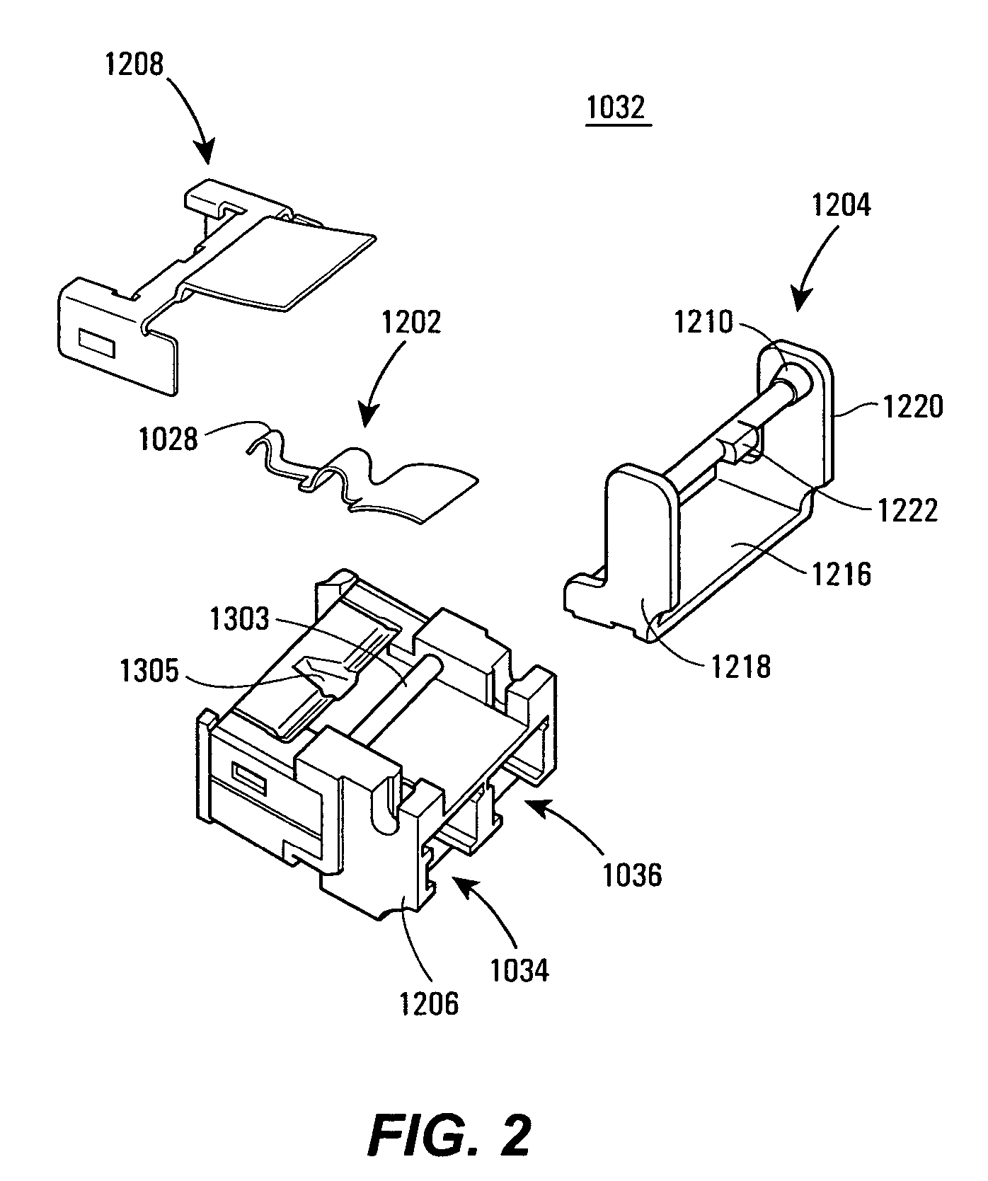
[0029]Numerous examples are provided of latching mechanisms that may be selectively latched and delatched with a casing. The examples may be used with, and are described in relation to, an optical module that may be plugged into a cage. Although example optical modules are described, such as small form factor pluggable (SFP) optical transceivers, the present disclosure is not limited to such example devices. Furthermore, while some example implantations are illustrated, persons of ordinary skill in the art will appreciate that other implementations may be used and, thus, fall within the present teachings.

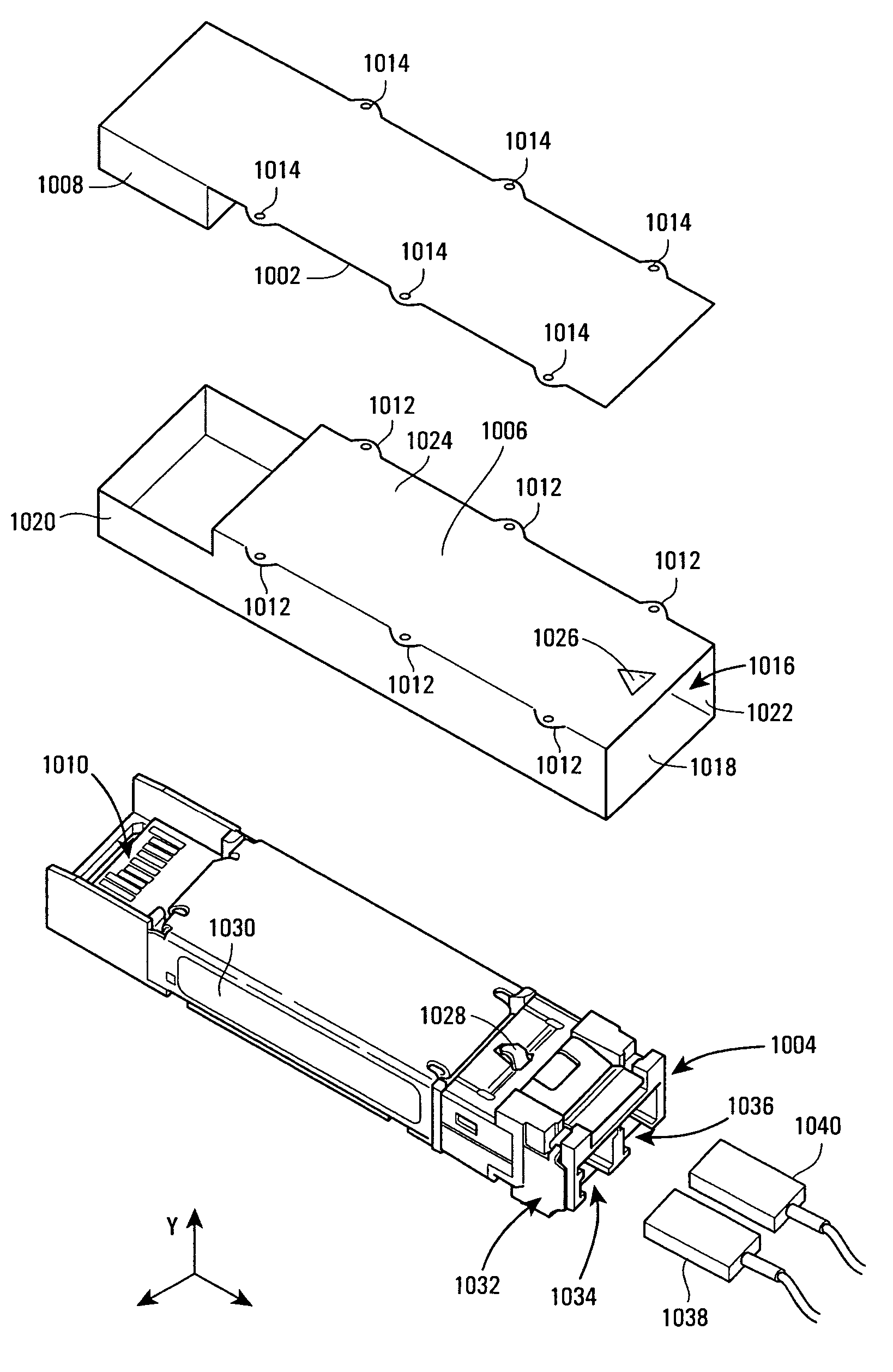
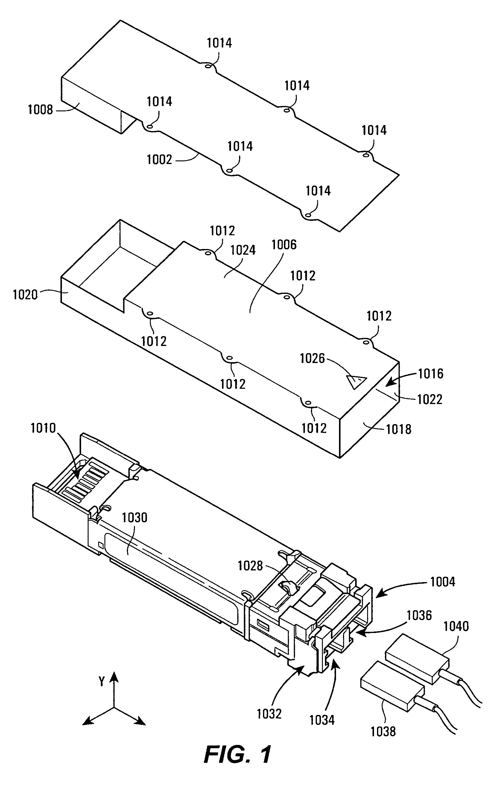
[0030]FIG. 1 illustrates an unassembled computer board assembly 1000 that includes a host board 1002, an optical module 1004, and a cage 1006. The assembly 1000 may be part of processor-based system, such as a switch, router, server, or personal computer. Example standards for such system devices include asynchronous transfer mode (ATM), fiber-distributed data interface (FDDI), Fibr...


PUM


Abstract

An optical module that may be used in small-form factor pluggable applications includes a delatching / latching mechanism. The optical module may be an optical transceiver, for example, and the delatching / latching mechanism may allow for improved insertion and removal of the optical module from a cage in a computer board assembly. A latching assembly that assists in latching and delatching may include a latching member having a slotted mating element that is in contact with, and rotates relative to a substantially-fixed pivot element. Rotation may be achieved via a rotatable actuator having a cam engaging a cam follower. Numerous example biasing apparatuses are described to bias the latching assembly to its latched position and to promote contact between the mating element and the pivot element.

Description

CROSS-REFERENCE TO RELATED APPLICATIONS[0001]This application claims the benefit of U.S. Provisional Application No. 60 / 549,861, filed on Mar. 2, 2004 entitled “Optical Module with Delatching Mechanism,” the entire application of which is hereby expressly incorporated herein by reference. This application claims the benefit of U.S. Provisional Application No. 60 / 550,554, filed on Mar. 3, 2004 entitled “Optical Module with Delatching Mechanism,” the entire application of which is hereby expressly incorporated herein by reference.FIELD OF THE DISCLOSURE[0002]The present disclosure relates generally to optical modules and, more specifically, to optical modules removably mountable within a cage or housing.BACKGROUND OF RELATED ART[0003]The promulgation of optical networks has been integral to the advancement of information technology. From local-, wide-, and metro-area networks to cable television networks, optical networks have brought increased services and information access to consu...

Claims


Application Information

Patent Timeline
Patent Type & Authority Patents(United States)
IPC IPC(8): G02B6/36G02B6/42H01R13/627H01R13/658H01R13/66
CPCG02B6/4292G02B6/4246H01R13/6581H01R13/665H01R13/6275
Inventor KIM, BRIAN H.WANG, WILLIAM H.
Owner SUMITOMO ELECTRIC DEVICE INNOVATIONS U S A
Why Eureka
Try Eureka