Ball joint with angular movement restriction system

a technology of angular movement and ball joint, which is applied in the direction of shafts, bearings, pivots, etc., can solve the problems of undesirable rotation relative to the longitudinal axle of the shaft, and inadequate operation of the ball join

Active Publication Date: 2006-08-01
DANA SPICER IND E COMERCIO DE AUTOPECAS LTDA
View PDF16 Cites 24 Cited by
  • Summary
  • Abstract
  • Description
  • Claims
  • Application Information

AI Technical Summary

Benefits of technology

[0009]In accordance with this invention, the ball joint with angular movement restriction system allows the free rotational movement of

Problems solved by technology

The movement restriction system according to the preferred embodiment is applied in steering or connecting rods where movement of rotation relative to the longitudinal axle thereof is undesirable.
The rotational movement of the bar relative to its longitudinal axle for

Method used


Image

  • Ball joint with angular movement restriction system
  • Ball joint with angular movement restriction system
  • Ball joint with angular movement restriction system

Examples


Embodiment Construction

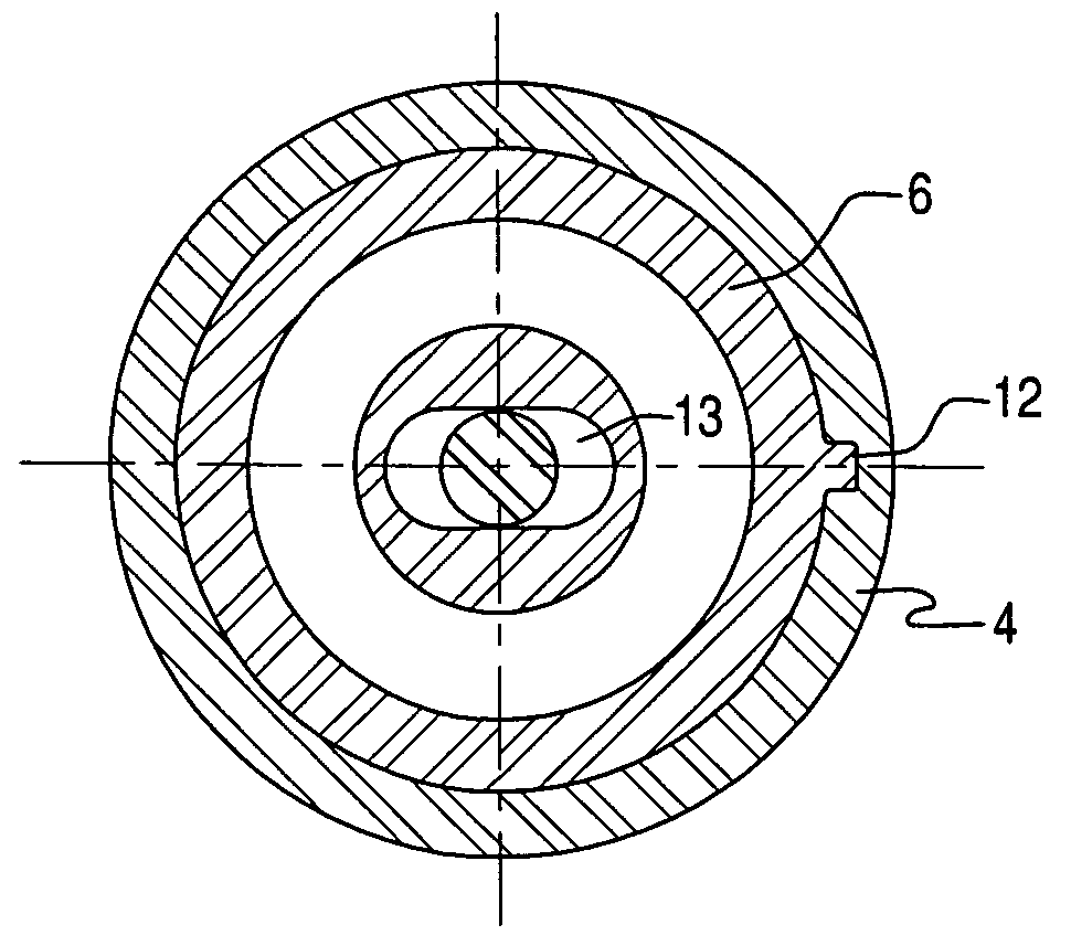
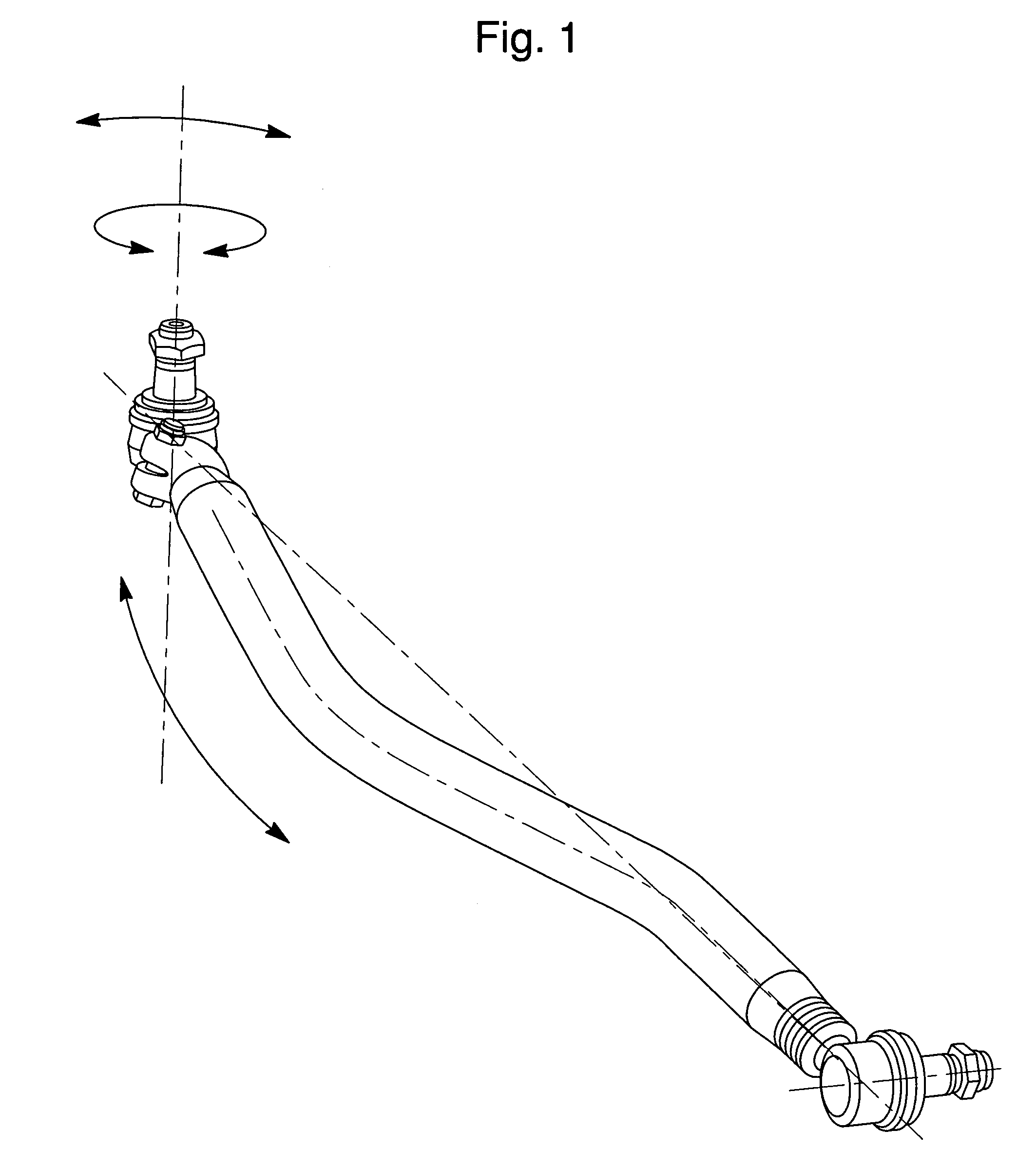
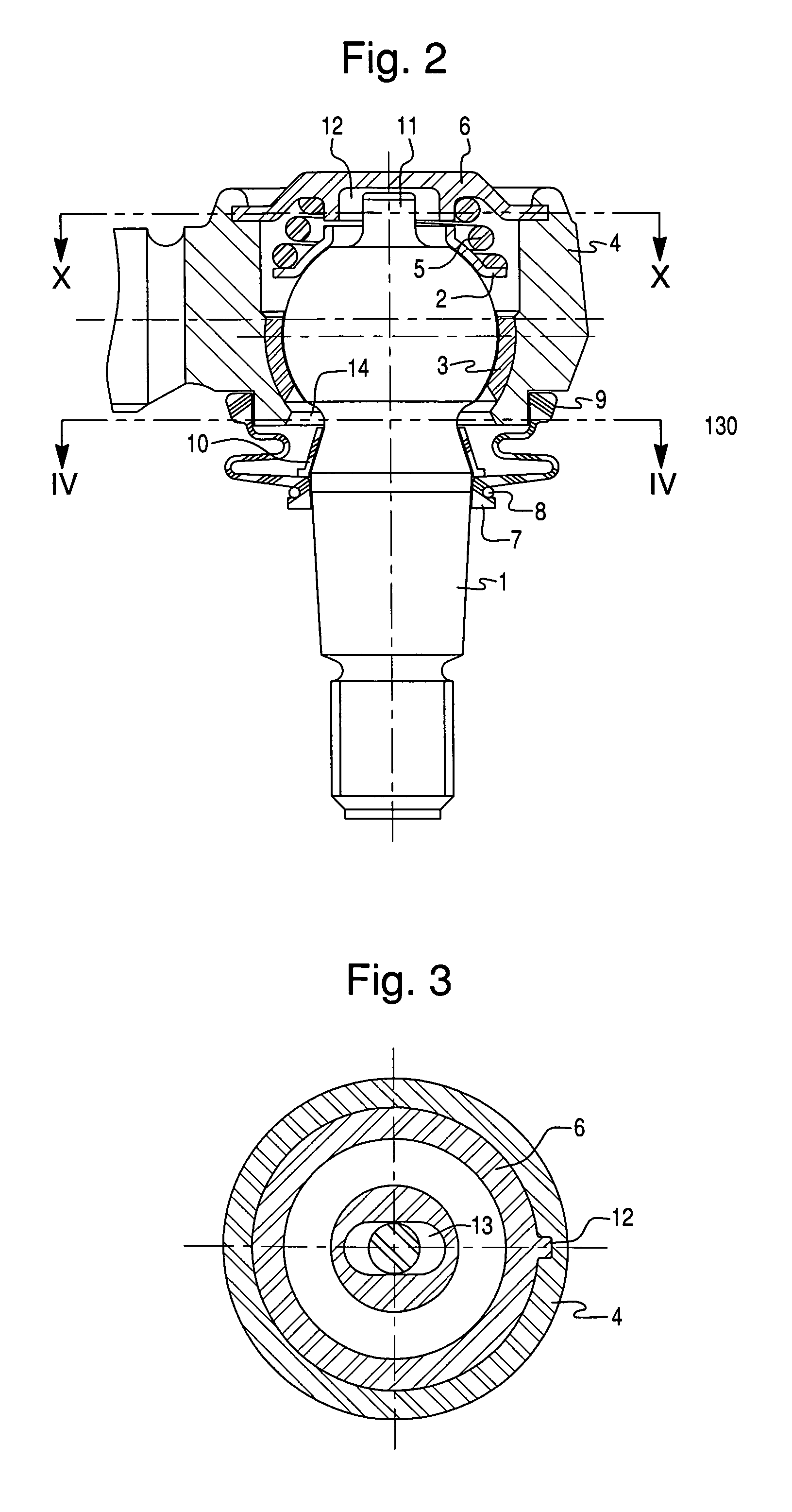
[0019]As it is seen in FIG. 2, the ball joint is constituted of a reinforcement pin 1 that is housed in an upper bearing member 2 and in a lower bearing member 3, and the assembly is mounted inside a box 4. Disposed inside the box 4 between the upper bearing member 2 and a cover is a spring 5. The spring 5 is introduced through an opening that is later closed by the cover 6. The ball type pin 1 projects through an end of the box 4 opposite the opening closed by the cover 6. The ball type pin 1 is fixed to a first member, i.e., a connecting rod shown in FIG. 1, and the external part of the box 4 is fixed to a second member, i.e., a steering component of an automotive steering system, so that the restricted angular and free rotational movements produced by the ball type pin 1 relative to the box 4 is transmitted to these first and second members thus satisfying the movement requirements demanded by the same.

[0020]On the body of the ball type pin 1 there is provided a sealing cover 7 t...


PUM


Abstract

A ball joint restriction system provides a cylindrical extension in the end of the ball, and also provides an oblong housing in the closing cover of the ball joint to restrict movement of the extension. A positioning member positions the cover with respect to the box so that the oblong opening of the housing is provided in the same direction that the oblong opening in the other end of the ball joint box, through which pin or stem of the ball type pin passes. The ball joint will guarantee the maintenance of the connecting rod, whatever is its curve and weight, perfectly aligned with the other components of the system, as well as it will allow that the ball type pin to be always positioned in its designed geometrical axle.

Description

BACKGROUND OF THE INVENTION[0001]1. Field of the Invention[0002]This invention refers to a ball joint with angular movement restriction system, for application in connections which require angular and rotational movement of two pieces, but whose angular movement needs to be restricted in a certain direction in order to achieve the desired effect, and more particularly, this invention is related to a ball joint to be applied in automotive vehicles.[0003]2. Description of Related Art[0004]Conventional construction of ball joints is based on a construction composed of a box or receptacle where there is housed a bearing, of single or split type, that houses a ball that is disposed as an integral part of the extremity of a pin, a so-called ball type (or ball) pin.[0005]This set, duly mounted, has a fixing system in the external part of the box or receptacle, disposed at the extremity opposed to the ball, of the so-called ball type pin, in such a way that, when mounted in the box, it prov...

Claims


Application Information

Patent Timeline
IPC IPC(8): F16C11/06
CPCF16C11/0604F16C11/0619Y10T403/32754Y10T403/32631Y10T403/32762Y10T403/32811F16C11/0647
Inventor PADUANO, ENZO
Owner DANA SPICER IND E COMERCIO DE AUTOPECAS LTDA
Why Eureka
Try Eureka