Collapsible container with dunnage erection biaser

a dunnage erection and container technology, applied in the field of shipping containers, can solve the problems of not much of a shipping cost saving when returning empty reusable containers, the cost of storing conventional reusable containers may further reduce the other economic benefits they offer, and still be relatively costly to provide for their return shipment. the effect of reducing the force needed to erect the containers

Inactive Publication Date: 2006-08-01
BRADFORD CO
View PDF19 Cites 36 Cited by
  • Summary
  • Abstract
  • Description
  • Claims
  • Application Information

AI Technical Summary

Benefits of technology

[0020]For retaining product within the container, collapsible dunnage spans between at least two side structures. In one embodiment, the dunnage is movable to an erected position for receiving product when the side walls and frame are erected. The dunnage also moves to a collapsed position in the container body when the side walls and frame are collapsed, so that the dunnage remains with the container when returned. In that way, the dunnage in the container is also reusable, reducing dunnage replacement costs, and also reducing and / or eliminating labor costs associated with handling and discarding used dunnage from a container and assembling new dunnage prior to the container being loaded with product and shipped.
[0021]In a preferred embodiment, the container has an open side for horizontal loading of product into the dunnage. The open side is in alignment with the dunnage for providing access to the dunnage and product within the dunnage from the side of the container. The product in the container may thus be transferred into and out of the container easily and efficiently in a process known in the art as horizontal loading. The present invention is particularly useful for assembly line use as product in the container may be removed and transferred to an assembly line in one smooth movement. Unnecessary lifting of the product is reduced and / or eliminated to further assist an assembly line worker or other person using the shipped products.
[0024]Due at least in part to the dunnage erection biasers, the present invention reduces the force needed to erect the containers and attached dunnage.

Problems solved by technology

Furthermore, the returned containers alleviate the assembly plant's task and associated costs with storing, destroying, or otherwise disposing of the containers.
While returnable and reusable containers reduce costs by eliminating the need to constantly purchase new containers and reduce disposal costs, it may still be relatively costly to provide for their return shipment.
Therefore, there was not much of a shipping cost savings when returning empty reusable containers even though empty containers weighed less.
Furthermore, the cost of storing conventional reusable containers may further reduce the other economic benefits they offer because empty containers also require the same warehouse or storage space as full containers.
Storage space is valuable and may be limited, and it is usually desirable to utilize the space for something other than bulky, empty containers waiting to be shipped or returned.
Additionally, collapsed, stored containers require substantially less storage space.
While such containers address the issue of return shipment and storage costs, they still have certain drawbacks.
The dunnage elements are then discarded or otherwise disposed of by the assembly plant, further adding to the plant's overall cost for the shipment.
Furthermore, the supplier incurs additional costs by constructing or acquiring new dunnage elements each time the returned container is reused.
Additionally, the labor costs associated with constructing and installing dunnage elements in a container, and the additional labor for collapsing, removing and disposing of the dunnage elements after shipment, further increases the overall cost of shipping product utilizing conventional containers.
Therefore, even with existing collapsible, returnable containers, high shipping costs may be incurred on both ends, i.e., by the supplier who constantly acquires new dunnage elements and by the assembly plant which constantly must dispose of the old dunnage elements or pay to have those dunnage elements returned with the container.
Moreover, dunnage elements, depending on the size of the container, may be heavy, and as such, the assembly of the dunnage elements to accept a product can be physically stressful for the worker and may lead to job related injuries.
Job related injuries increase costs.
Additionally, because someone must physically assemble the dunnage, the dunnage elements and the containers have been limited in size and weight in accordance with what an average worker can physically and safely erect.
However, access to some existing containers may be difficult when removing a parts to install.
Because, a line worker only has a certain amount of time to install a part, any delay in accessing a part is undesirable.
Furthermore, the repetitive motion of accessing parts to install on a vehicle from some containers can be difficult or straining to line workers since it must be done many times during a shift.
Likewise, repetitively having to assemble or erect a dunnage structure can be wearisome for workers.

Method used


Image

  • Collapsible container with dunnage erection biaser
  • Collapsible container with dunnage erection biaser
  • Collapsible container with dunnage erection biaser

Examples


Embodiment Construction

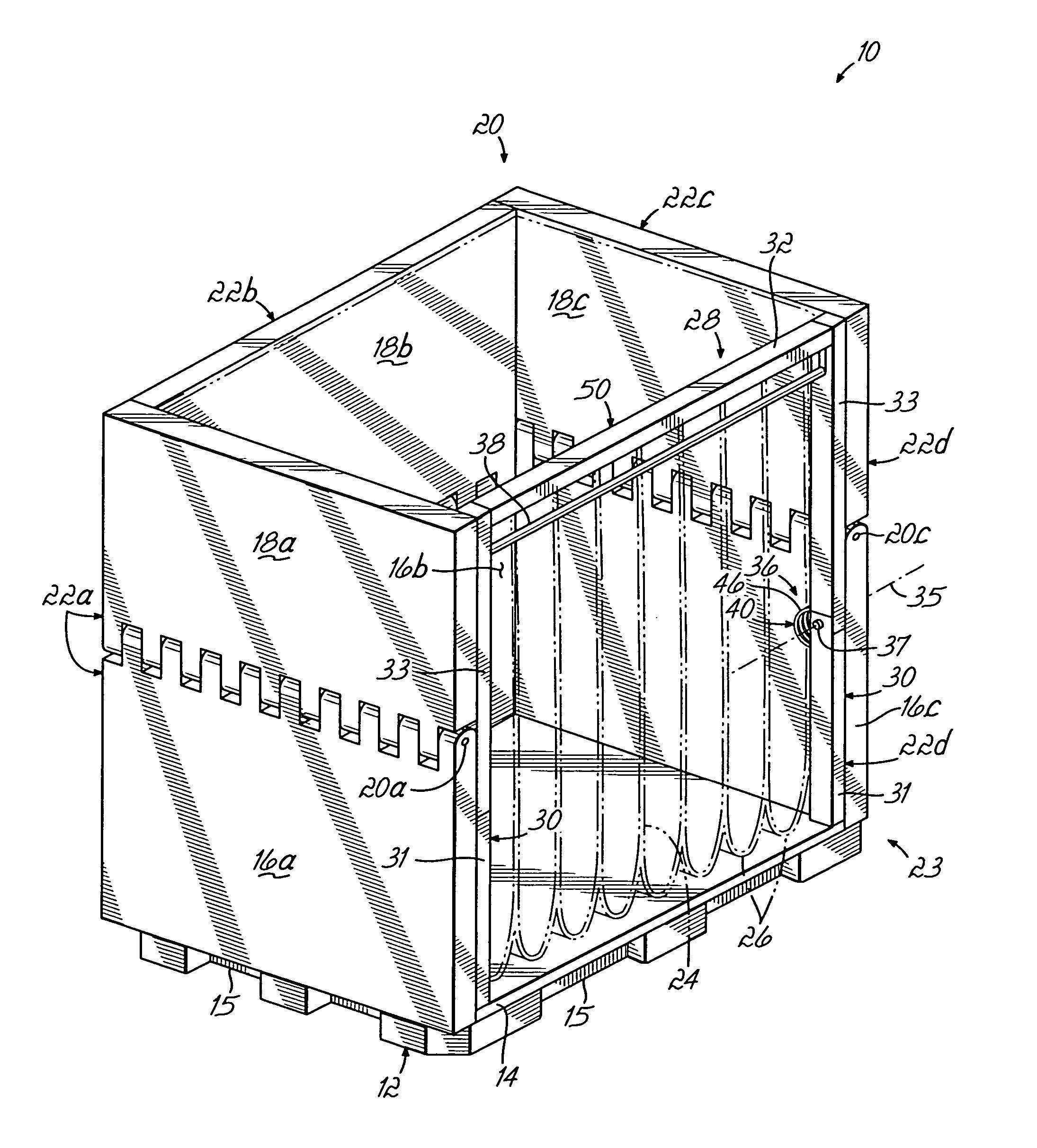
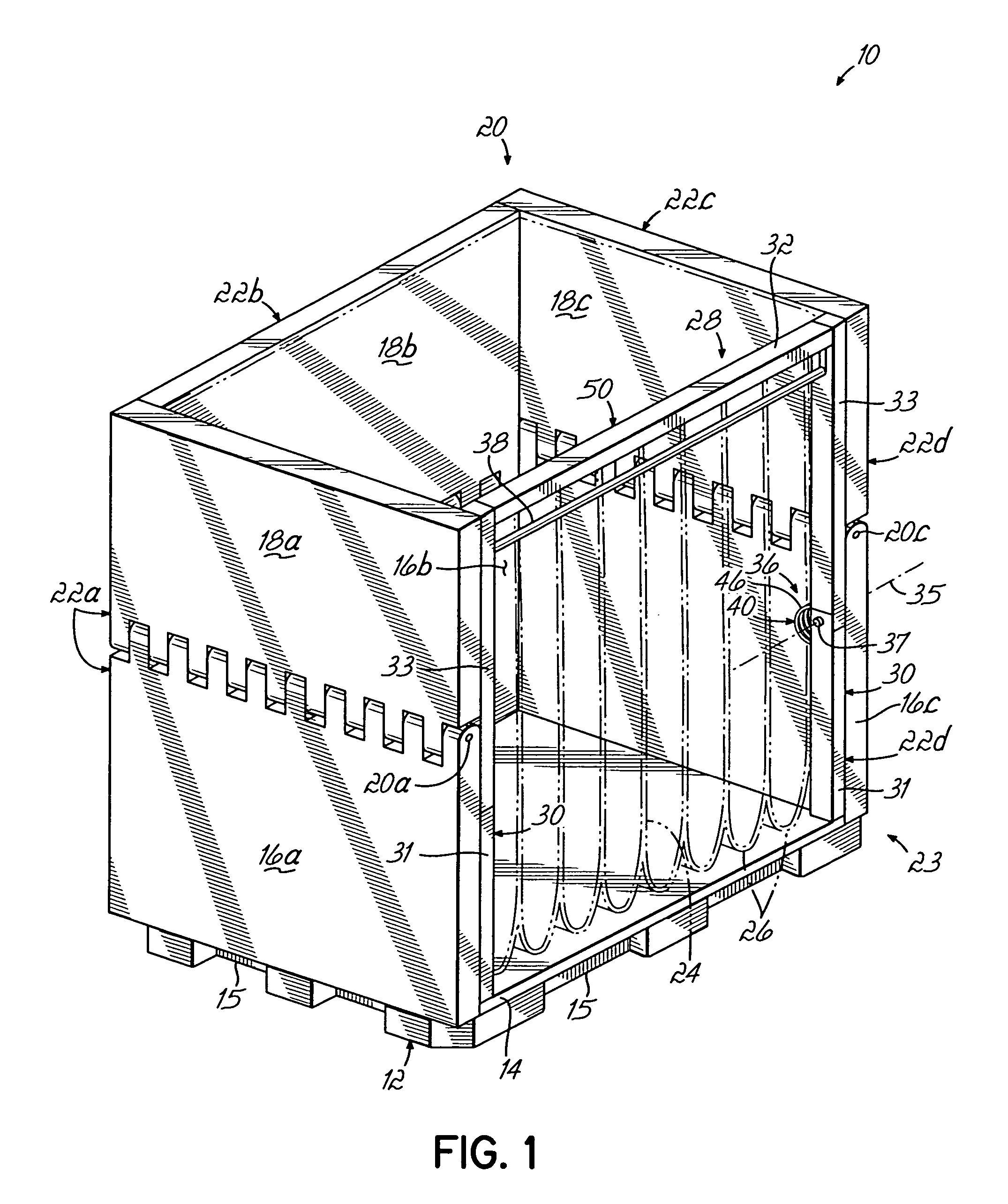
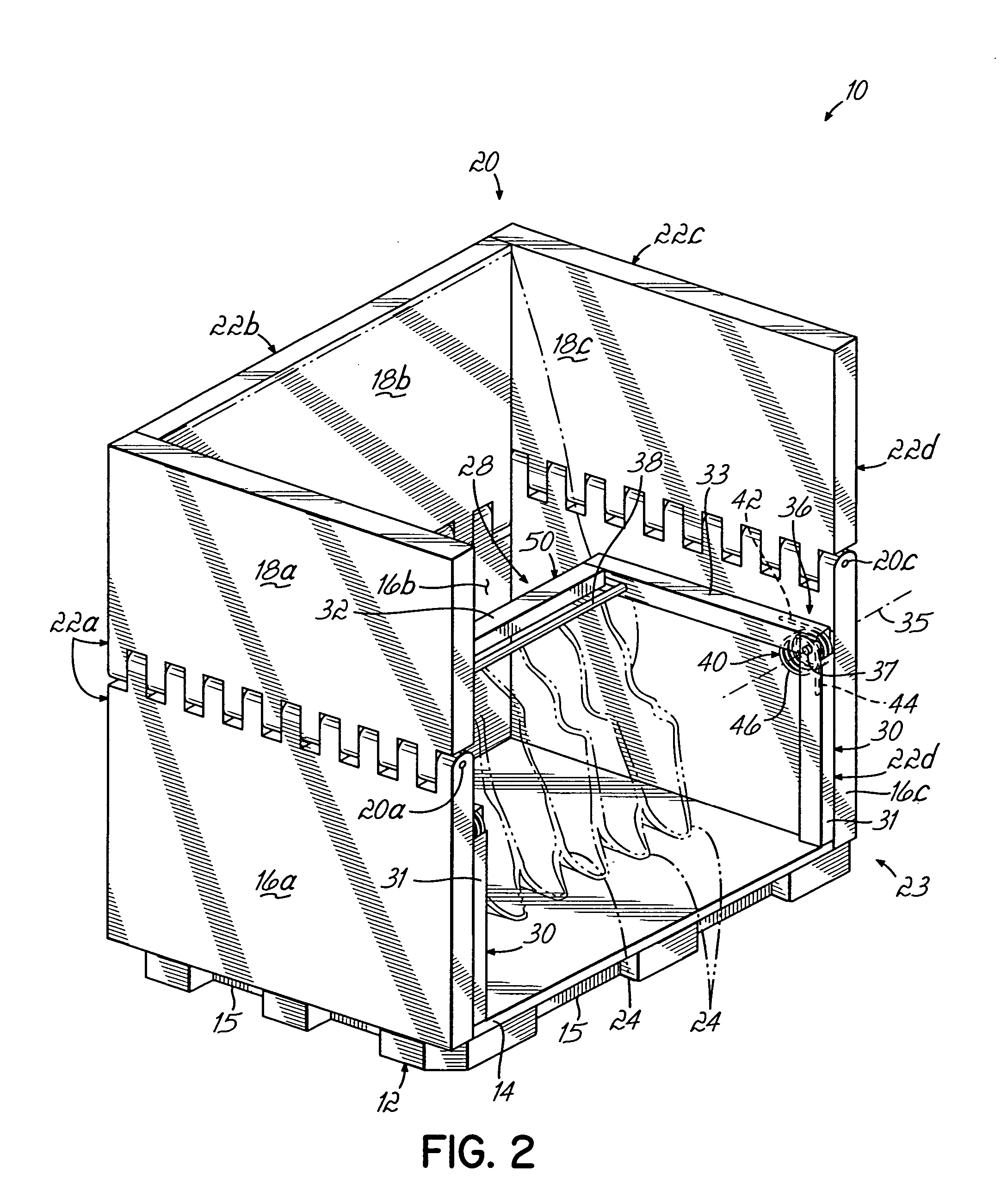
[0032]FIG. 1 shows a container 10 having a base 12 having a bottom portion 14 and three fixed, upstanding vertically oriented wall portions 16a, 16b and 16c extending upwardly from the perimeter of the bottom portion 14 of the base 12. A rear wall 18b and side walls 18a, 18c are hingedly connected to the vertically oriented wall portions 16b and 16a, 16c of the base 12, respectively. Side wall 18a is hingedly or pivotally joined to the wall portion 16a of the base 12 with a hinge pin 20a so that the side wall 18a may move or pivot from a collapsed position shown in FIG. 3D to an erected position shown in FIG. 3A. Similarly, rear wall 18b is hingedly or pivotally joined to the wall portion 16b of the base 12 with a hinge pin 20b (see FIG. 3A) so that the rear wall 18b may move or pivot from a collapsed position shown in FIG. 3D to an erected position shown in FIG. 1. Lastly, side wall 18c is hingedly or pivotally joined to the wall portion 16c of the base 12 with a hinge pin 20c so t...


PUM


Abstract

A reusable and returnable container for holding product therein during shipment and subsequently being returned without product comprises a body having at least two opposed side structures, collapsible dunnage operably connected to the side structures, and a dunnage erection biaser operably connected to one of the side structures. The force needed to erect the dunnage is minimized due to the dunnage erection biaser. The dunnage erection biaser, in one embodiment is a pair of torsion springs. However, the biaser may be any elastic or non-elastic device to facilitate erection of collapsed dunnage.

Description

FIELD OF THE INVENTION[0001]The present invention relates generally to shipping containers used to ship products, and more specifically to collapsible containers which are returnable in an empty state for reuse.BACKGROUND OF THE INVENTION[0002]Returnable and reusable containers are utilized by manufacturers to ship a variety of different products to end users, such as assembly plants. For example, an automobile assembly plant utilizes parts from a number of different parts manufacturers or suppliers. These suppliers ship their respective parts to the assembly plant in reusable containers, and the parts are then removed from the containers, assembled into a finished product, and the empty containers are then returned to the parts suppliers for use in subsequent shipments.[0003]The return and reuse of empty containers results in a substantial cost savings for the supplier and / or the end manufacturer or assembler because reuse reduces the number of new containers which must be purchase...

Claims


Application Information

Patent Timeline
Patent Type & Authority Patents(United States)
IPC IPC(8): B61D3/16
CPCB65D19/12B65D19/44B65D2519/00164B65D2519/00169B65D2585/6882B65D2519/00502B65D2519/00666B65D2519/0082B65D2519/00875B65D2519/00174Y02W30/80B65D81/05
Inventor NYEBOER, CALVIN D.
Owner BRADFORD CO
Why Eureka
Try Eureka