Low profile head gimbal assembly with shock limiting and load/unload capability

a low-profile, gimbal technology, applied in the direction of data recording, instruments, magnetic recording, etc., can solve the problems of increasing the potential for damage caused, weakening the magnetic field produced by the poles, and contact between the slider and the disk

Inactive Publication Date: 2006-08-01
WESTERN DIGITAL TECH INC
View PDF32 Cites 52 Cited by
  • Summary
  • Abstract
  • Description
  • Claims
  • Application Information

AI Technical Summary

Problems solved by technology

However, as the poles are made smaller, the magnetic fields produced by the poles become weaker.
Unfortunately, flying a slider close to the disk surface increases the potential for damage caused by the slider contacting the disk surface.
Contact between the slider and disk can result from a shock, jolt or bump to the disk drive, or from the process of loading and unloading the slider between uses.
Depending on the flying height of the slider, even a relatively minor shock can displace the slider enough to cause it to collide with the disk surface.
Also, an external shock or jolt to the disk drive can cause structural damage to the flexure if the slider is displaced too far about, or from, the pivot point or if the flexure is loaded excessively.
Such shocks or jolts can also occur during the manufacturing process when the disk drive is assembled.
Damage to the flexure can include dimple separation and bending of the flexure.
With dimple separation the flexure no longer can maintain the slider in contact with the pivot point or even if contact can be maintained it cannot be done with the same resiliency.
Slider contact with the surface of the disk causes both the slider and the disk surface to sustain some wear.
Stiction may cause structural damage to the delicate head gimbal assembly.
Stiction causes further wear of the slider and disk surface as well as the load on the motor turning the disk.
In a disk drive having a load / unload ramp, the space between disks is limited by the height of lifter tabs of the head gimbal assemblies.
As such, the height of the lifter tab directly limits the spacing between disks, which in turn limits the disk stack density.

Method used


Image

  • Low profile head gimbal assembly with shock limiting and load/unload capability
  • Low profile head gimbal assembly with shock limiting and load/unload capability
  • Low profile head gimbal assembly with shock limiting and load/unload capability

Examples


Embodiment Construction

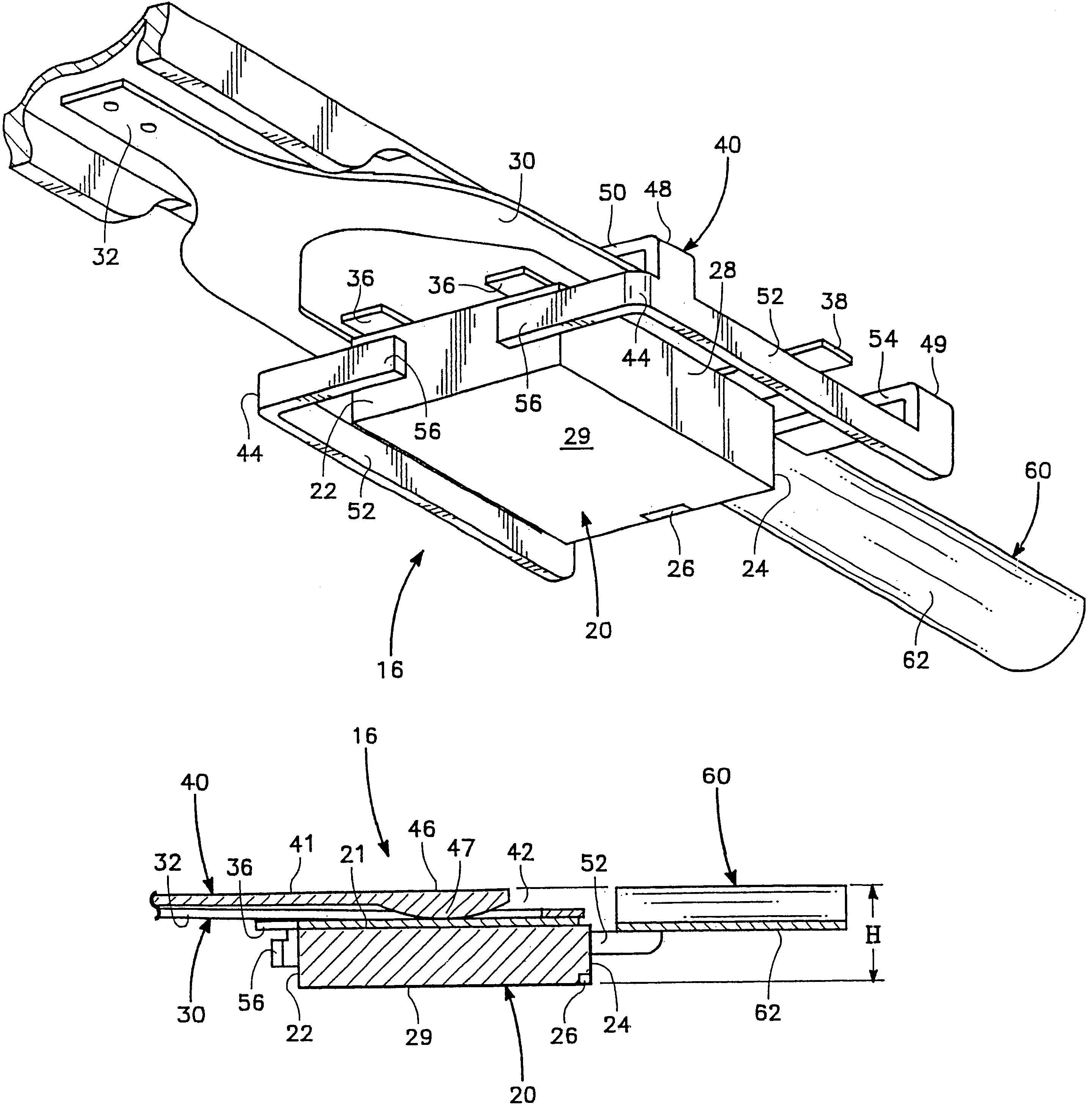
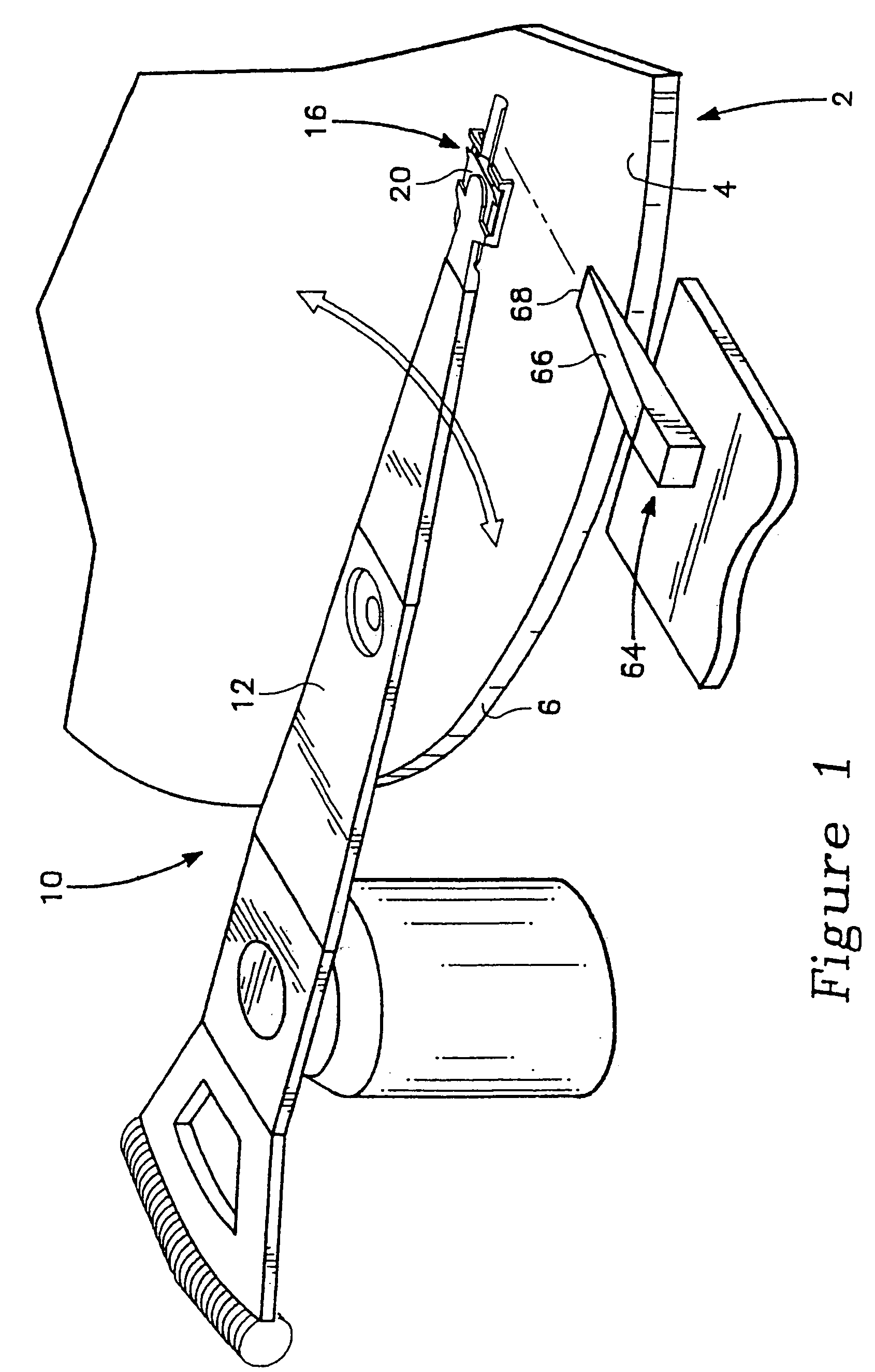
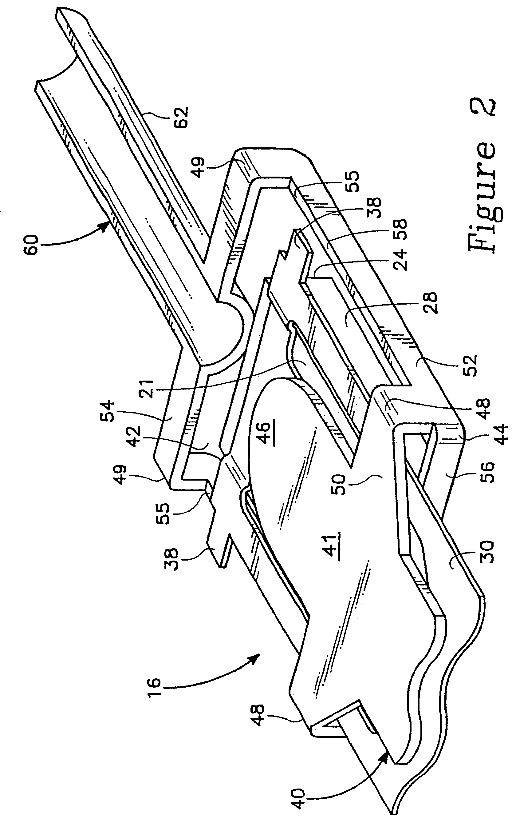
[0030]In the preferred embodiments the invention is embodied in a head gimbal assembly (HGA). The head gimbal assembly includes an apparatus for limiting the pitching, rolling and vertical displacement of the slider relative to the supporting structure of the head gimbal assembly. This limiting apparatus reduces the possibility of damage to the head gimbal assembly and disk from collisions between the slider and disk caused by shocks or jolts to the disk drive from external sources and the manufacturing process. Collisions are also avoided as the head gimbal assembly is configured to produce a positive pitch of the slider during load and unload operations. The head gimbal assembly is also configured to have a low overall height. This height reduction is achieved by reducing the height of the lifter tab in a manner which still allows for load and unload operations. The low profile of the head gimbal assembly allows for a significant increase in stack density. That is, the low profile...


PUM

PropertyMeasurementUnit
sizeaaaaaaaaaa
recording densityaaaaaaaaaa
magneticaaaaaaaaaa

Abstract

Head gimbal assemblies are provided that comprise a slider, a load beam, a flexure, and a lifter tab. The flexure holds the slider against a pivot point of the load beam. The lifter tab extends from the load beam to engage a load / unload ramp. The load beam includes a base portion having the pivot point, a first side rail, and a first limiter stop. The first side rail is disposed adjacent to a transverse side of the slider while the first limiter stop is adjacent to a leading side of the slider. The first limiter stop extends from the first side rail and is essentially perpendicular thereto. The flexure includes a first leading edge tab that extends between the first limiter stop and the base portion of the load beam to limit the movement of the flexure especially during loading and unloading.

Description

CROSS-REFERENCE TO RELATED APPLICATIONS[0001]The present patent application is a continuation of U.S. patent application Ser. No. 10 / 379,778, filed Mar. 4, 2003 now U.S. Pat. No. 7,010,847 and entitled “Method of Manufacturing a Head Gimbal Assembly with Substantially Orthogonal Tab, Side Beam, and Base,” which is a divisional of U.S. Pat. No. 6,538,850, issued Mar. 25, 2003, and entitled “Low Profile Head Gimbal Assembly with Shock Limiting and Load / Unload Capability and Method of Manufacture Thereof.”BACKGROUND OF THE INVENTION[0002]1. Field of the Invention[0003]The invention relates generally to disk drives, and more particularly to disk drive head assemblies.[0004]2. Description of the Prior Art[0005]As computers have improved over recent years the need for increased data storage has risen dramatically. To meet this need several approaches have been taken to make disk drives capable of storing more data without increasing, and in some cases actually decreasing, their overall si...

Claims


Application Information

Patent Timeline
Patent Type & Authority Patents(United States)
IPC IPC(8): G11B5/48G11B5/54
CPCG11B5/4826G11B5/6005G11B5/54G11B5/40
Inventor HADIAN, JAFARBOZORGI, JAMSHID
Owner WESTERN DIGITAL TECH INC
Why Eureka
Try Eureka