Support fixture and method for supporting subscriber specific fiber optic drop wire

a technology of support fixture and drop wire, which is applied in the direction of optics, optical light guides, instruments, etc., can solve the problems of time-consuming coils of the poles, unsuitable devices specifically intended for fiber optic cables, and unsightly appearance, and achieve the effect of simplifying the routing of drop cables

Active Publication Date: 2006-08-01
HUBBELL POWER SYST INC
View PDF6 Cites 17 Cited by
  • Summary
  • Abstract
  • Description
  • Claims
  • Application Information

AI Technical Summary

Benefits of technology

[0014]An object of the invention is to simplify the routing of drop cables from a cable closure. Another object is to permit an installer to store excess drop cable in loops supported by bend radius protectors.
[0020]The drop wire retainer clip of the present invention is designed to retain a multiplicity of drop wires that the invention is designed to accommodate as well as the need to facilitate a unique characteristic of a fiber optic drop wire installation. Unlike a cable installation, where the cable is a one-time installation intended to accommodate a multitude of subscribers over a long span of time, the fiber optic drop wire is an addition to the initial cable installation that is installed only when a new subscriber location is identified and ordered for service. This means that any number of additional drop wires may be added to the existing aerial plant structure from time to time. While the aerial cable run is normally within the right-of-way of the road where the pole line is routinely cleared of tree branches and the like making the line proper less likely to be damaged during a storm, the drop wire installation must enter and span private property where the potential for damage is more likely and thus the potential for the need to access the wire-retaining area of the support bracket to replace a drop wire could be more frequent. In conventional cable installations, tie-wrap type devices have been used to secure the cable from dislodgement from the support bracket. Since the need to access or remove a cable from a support bracket is relatively rare, the tie-wrap represents a practical means for this particular use. In contrast, in the application of fiber optic drop wire, where the need to access the wire-retaining area of the support bracket will be relatively frequent, the use of tie-wraps to secure the wire-retaining area is impractical due to the fact that each incident of access requires cutting and discarding the existing tie-wraps and then re-installing new tie-wraps when the task is completed. Installation personnel, particularly those employed on a subcontract basis, cannot always be relied upon to replace tie-wraps that were removed thereby exposing the drop wires to potential damage. Therefore, there is a need to provide for a means to retain the drop wires within the channel portion of the apparatus which does not have to be removed during an installation or repair operation but, at the same time, allows for easy access to the wire-retaining area of the support bracket. The retainer clip of the present invention provides such a benefit. In use, the clip is installed into its respective indexing slot along the periphery of the channel portion of the support bracket. When access to the inner area of the channel is required, applying pressure to the protruding tab may open the clip, and then allowing the tab to spring back into place re-closes the accessed area. Thus the retainer clip remains in place throughout the operation and the drop wires remain properly secured at all times.
[0021]The recessed slot located in the cross-brace portion of the invention provides an indexing means by which either a standard messenger mounting bracket or an ADSS mounting bracket can be attached in a manner that prevents rotation of the support bracket in relation to the mounting bracket about the mounting bolt if or when pressure is applied to the channel as a result of the fiber optic drop wire installation process. Without such a securing means, the need to constantly realign the support bracket during the installation process would be a distinct possibility. A cable installation, by contrast, uses a support bracket with two mounting points in-line with the cable run from which it is suspended making rotation of the support bracket virtually impossible. With the fiber optic support bracket, the use of two mounting points would be impractical. Therefore, a means to arrest possible rotation is required and the means provided by the present invention addresses this requirement in the most practical manner.

Problems solved by technology

However, prior devices specifically intended for fiber optic cable are not necessarily applicable to fiber optic drop wire, which has only recently been put into use.
The reverse point of the fiber optic drop cables does not have the bend radius protected and the coils of the pole are time consuming and very unsightly since each splice closure can have as many as 16 separate drop cables exiting it.

Method used


Image

  • Support fixture and method for supporting subscriber specific fiber optic drop wire
  • Support fixture and method for supporting subscriber specific fiber optic drop wire
  • Support fixture and method for supporting subscriber specific fiber optic drop wire

Examples


Embodiment Construction

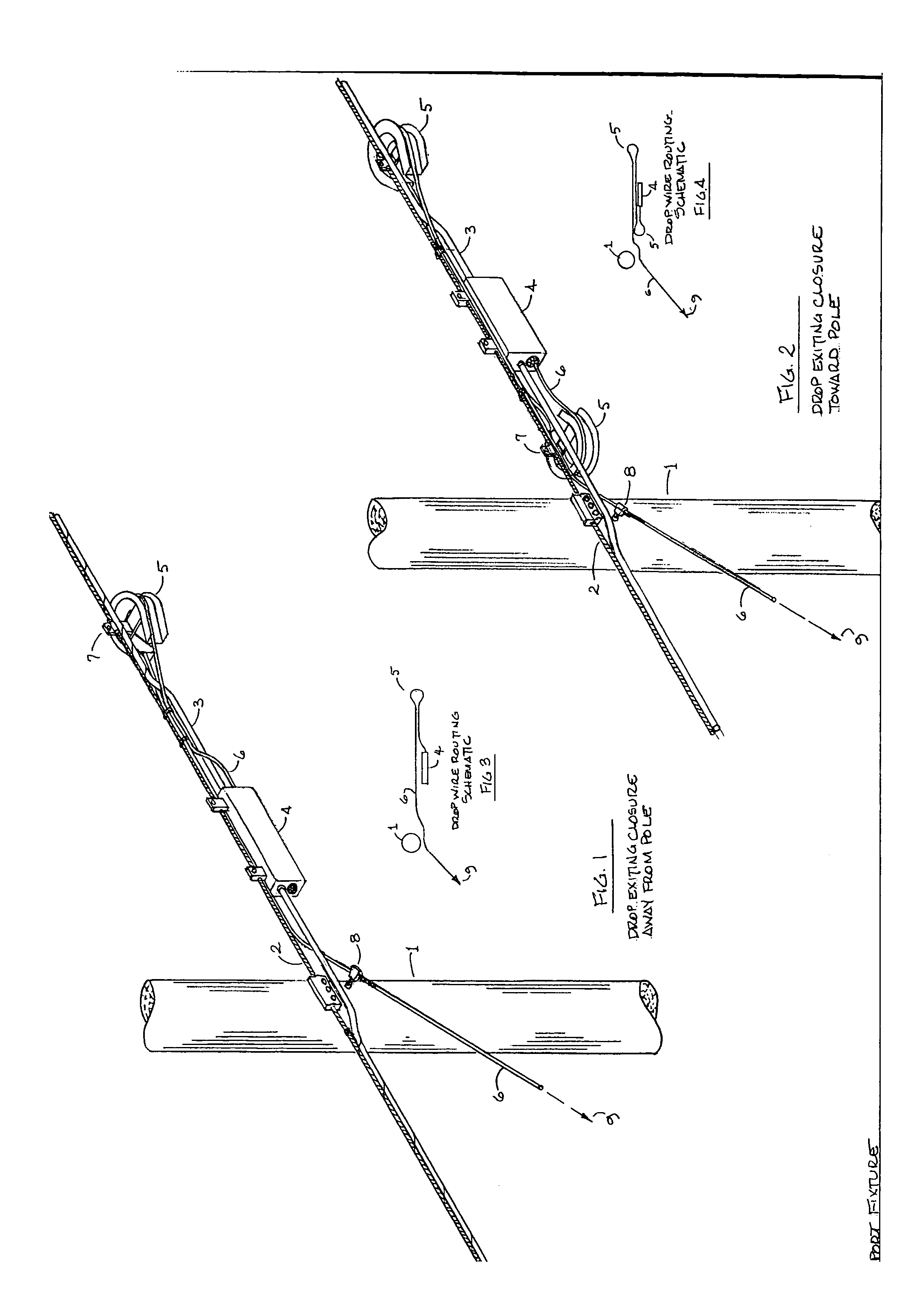
[0030]A fixture embodying the invention, shown in FIG. 1, includes a horseshoe-shaped bend radius protector 5 having two flanges defining an external channel for containing plural fiber optic drop wires. The protector 5 is suspended by a bracket 7 from a steel messenger cable 2 which is secured to a pole 1 by a clamp. A fiber optic cable 3 running along the messenger is secured to the messenger cable by wrapping. The cable closure 4 contains optical connectors which pass signal from the main cable to one or more drop wires 6. In most cases, three to sixteen drop wires extend from each cable closure; however, only one is shown in the drawing for the sake of clarity. The external channel of each bend radius protector is large enough to support from three to sixteen drop wires.

[0031]The cable closure has two ends: one near the pole and one further away. In the arrangement of FIG. 1, a drop wire extends from the further end in a direction away from the pole. It is tied to the messenger ...


PUM


Abstract

Fiber optic drop wires extending from a cable closure supported along a fiber optic cable are supported by small horseshoe-shaped bend radius protectors which not only prevent overbending of the drop wires, but also enable one to store excess drop wire length on the bend radius protectors. The free end of the drop wire is clamped to a utility pole.

Description

[0001]This application is a continuation-in-part of copending application Ser. No. 10 / 829,458, filed Apr. 22, 2004.BACKGROUND OF THE INVENTION[0002]This invention relates to a support fixture and method for supporting subscriber specific fiber optic drop wire.[0003]The invention relates generally to a method of aerially supporting lengths of fiber optic drop wire for subscriber applications, and more specifically, to an apparatus for supporting multiple lengths of fiber optic drop wire while maintaining a specified minimum bend radius.[0004]Means for aerially supporting surplus lengths of fiber optic cable and apparatus designed to maintain a minimum specified bend radius for such cable are well known. However, prior devices specifically intended for fiber optic cable are not necessarily applicable to fiber optic drop wire, which has only recently been put into use.[0005]While some of the of the requirements for installation of fiber optic drop wire are similar to that of fiber opti...

Claims


Application Information

Patent Timeline
Patent Type & Authority Patents(United States)
IPC IPC(8): G02B6/00G02B6/48
CPCG02B6/483
Inventor FORRESTER, JOSEPH H.
Owner HUBBELL POWER SYST INC
Why Eureka
Try Eureka