Network element management method, apparatus, and network management system

a network management and network element technology, applied in the direction of electrical apparatus construction details, data switching networks, instruments, etc., can solve the problems of inefficiency of conventional generation management methods using the logical numbers associated with mounting positions, inability to achieve efficient occupancy of bays, and inability to use slot b>1/b>

Inactive Publication Date: 2006-08-01
FUJITSU LTD
View PDF12 Cites 0 Cited by
  • Summary
  • Abstract
  • Description
  • Claims
  • Application Information

AI Technical Summary

Benefits of technology

[0057]Therefore, different from the conventional generation management model diagram shown in FIG. 19, it is made possible to perform a generation management with an efficient occupancy of the units whose mounting positions are unfixed.
[0070]Namely, by distinguishing the virtual object from the existing physical component to be managed with a blank area class, the third instance processing step can generate a blank area class instance apart from the physical class instance.

Problems solved by technology

In such a state where it is not required to fix the mounting positions of the units and the cards that are the physical components of the network unit, the conventional generation management method using the logical numbers associated with the mounting positions is inefficient.
Thus, when it is possible to flexibly change the mounting positions of the units on the bay, the occupancy of the bay cannot be achieved efficiently enough by the conventional generation management method.
This problem is common to the generation management of the cards mounted on the unit.
Moreover, the following problems exist in the management of the cards.
However, in case of performing a generation management without fixing the mounting positions of the cards, the element manager EMS is required to recognize that while the double-slot-width card is installed in the slot 3, the slot 1 cannot be used.

Method used


Image

  • Network element management method, apparatus, and network management system
  • Network element management method, apparatus, and network management system
  • Network element management method, apparatus, and network management system

Examples


Embodiment Construction

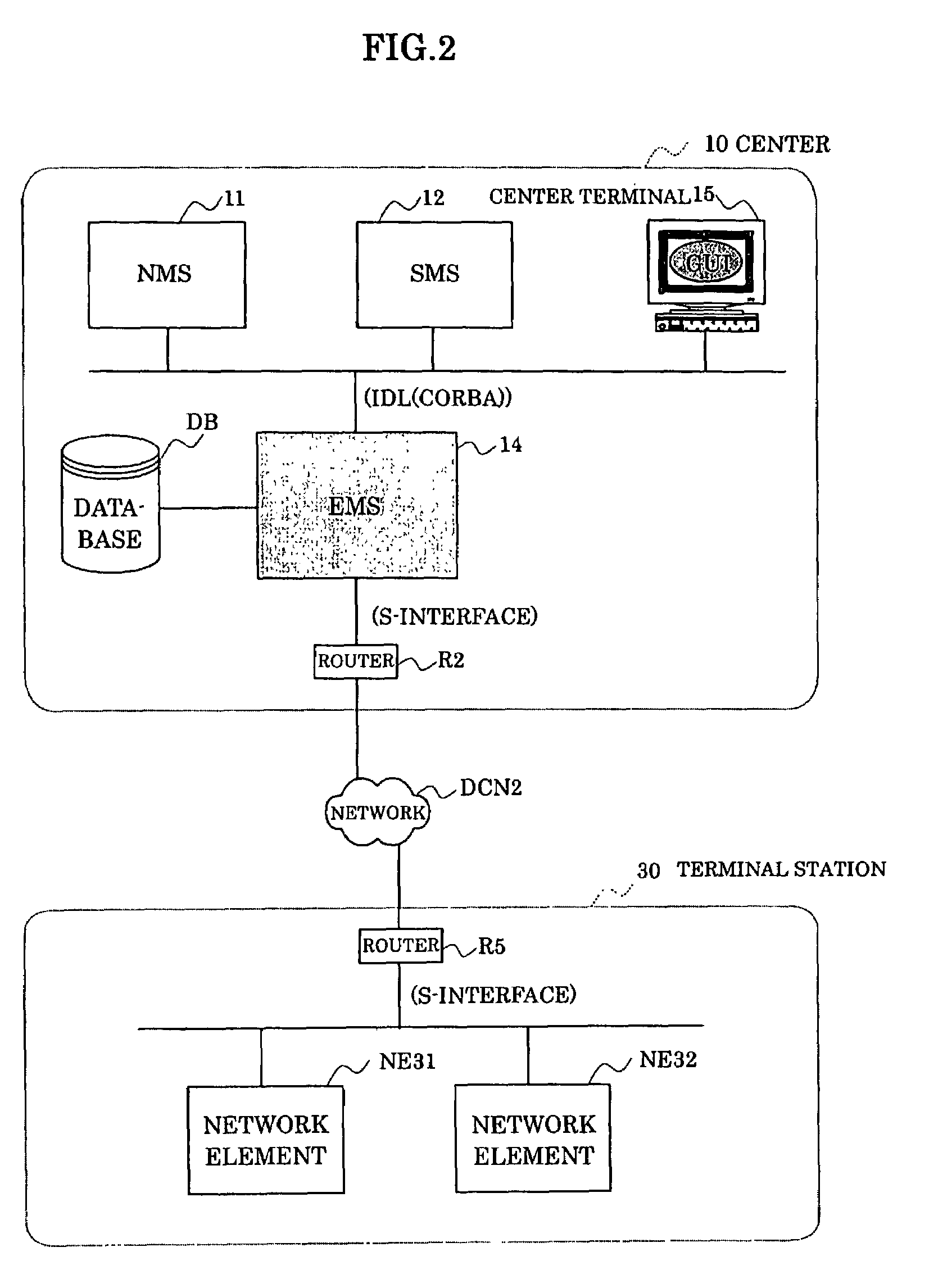
[0099]In order to describe an embodiment of the present invention, FIG. 2 shows a connection overview centering the element manager EMS of the general network management system shown in FIG. 14.

[0100]Since FIG. 2 shows only components related to the element manager EMS14 excerpted from the overall arrangement shown in FIG. 14, the accessory server group 13 in FIG. 14 is omitted. Also, while only the connection between the center 10 and the terminal station 30 is shown in FIG. 2, by reading the router R5, and the network elements NE31, NE32 respectively as the router R4, and the network elements NE21, NE22, the terminal station 30 can be read as the broadcasting station 20.

[0101]Also, in FIG. 2, a database DB is connected to the element manager EMS14 in the center 10. This database DB is for holding various tables referred to by the element manager EMS14.

[0102]As shown in FIG. 2, the element manager EMS14 uses an IDL(CORBA) as a communication protocol with the network manager NMS11, ...


PUM


Abstract

In a network element management method and apparatus, and a network management system where mounting positions of physical components on a network element are unfixed, an external input mounting schedule for a physical component detachable from a network element as mounting plan information including a type of the physical component, a scheduled mounting position within the network element, and a scheduled mounting term is received through a graphical user interface. No overlap with a preliminarily provided mounting schedule for another physical component per each predetermined measure of the scheduled mounting position is confirmed based on the inputted mounting plan information. The mounting plan information is determined to be implementable only when all of the predetermined measures of the scheduled mounting position are confirmed. Information of a holder class instance already generated in association with all of the predetermined measures of the scheduled mounting position is changed only when the mounting schedule is implementable, and a physical class instance associated with the holder class instance is generated.

Description

BACKGROUND OF THE INVENTION[0001]1. Field of the Invention[0002]The present invention relates to a network element management method, a network element management apparatus, and a network management system, and in particular to a method, an apparatus, and a system for managing a network element where mounting positions on physical components of a network element are unfixed.[0003]2. Description of the Related Art[0004]Generally, network management with respect to design, maintenance, operation, and the like of a network is performed hierarchically based on a telecommunication management network (TMN) having a concept for performing advanced network management.[0005]Management layers in the telecommunication management network TMN can be classified as shown in FIG. 13A into following layers: a service management layer SML for managing a service for customers, a network management layer NML for managing an entire network, and an element management layer EML for managing network elemen...

Claims


Application Information

Patent Timeline
Patent Type & Authority Patents(United States)
IPC IPC(8): G06F15/177G06F13/00H04L12/24H04L12/28
CPCH04L41/22H04L41/0233
Inventor NAKAMURA, TOSHIHIROOGURO, HIROYUKIYOKOSHI, NORIYUKIHAYASHI, MASAKIYANOKURA, YOSHINOBU
Owner FUJITSU LTD
Why Eureka
Try Eureka