
Modular switch with dynamic bus

a module switch and dynamic bus technology, applied in the field of communication networks, can solve the problems of limiting switches, large bandwidth of buses, and limiting switches, and achieve the effect of simplifying the management of sub-buses

Inactive Publication Date: 2006-08-01
LUCENT TECH NETWORKS +1
View PDF24 Cites 42 Cited by
  • Summary
  • Abstract
  • Description
  • Claims
  • Application Information

AI Technical Summary

Benefits of technology

[0015]Preferably, each card is allocated an initial first sub-bus for transmission. If the card requires additional bandwidth it is allocated more sub-buses until its needs are fulfilled. Thus, the card uses a variable fraction of its maximal capacity according to the needs of the ports of the card. In some preferred embodiments of the invention, a large number of relatively small sub-buses are defined, so as to increase the possibility of achieving an optimal allocation of the bus in which none of the cards is short of communication bandwidth. In other preferred embodiments of the invention, a small number of relatively large sub-buses are defined so as to simplify the management of allocation of the sub-buses.

Problems solved by technology

When the number of slots in the modular switch is relatively large and / or the amount of bandwidth needed by each card is large, the bandwidth of a bus which allows all the cards to transmit their entire capacity concurrently when all the slots are full with cards, may be very large.
These switches are limiting as they require that the cards be placed in specific slots or that the switch be configured each time a card is moved.
Such multiplexing, however, is wasteful as it gives all the cards the some amount of bandwidth regardless of their needs.
In addition, this solution adds delay to packets received by a card when it is not its turn to use the bus.
This solution, however, is too slow and complex for fast switches.
This solution is, however, expensive and inflexible.
The problem with this solution is that the packets themselves carry the direction information, and if this information is changed, intentionally or unintentionally, the packets may be passed through the wrong port.
These boxes, however, define a fixed border between the ATM and Ethernet switches and do not allow shifting of cards from one switch to the other, according to the current needs of the user.
Such conversion cards are naturally more complex than simple single protocol cards.

Method used


Image

  • Modular switch with dynamic bus
  • Modular switch with dynamic bus
  • Modular switch with dynamic bus

Examples


Embodiment Construction

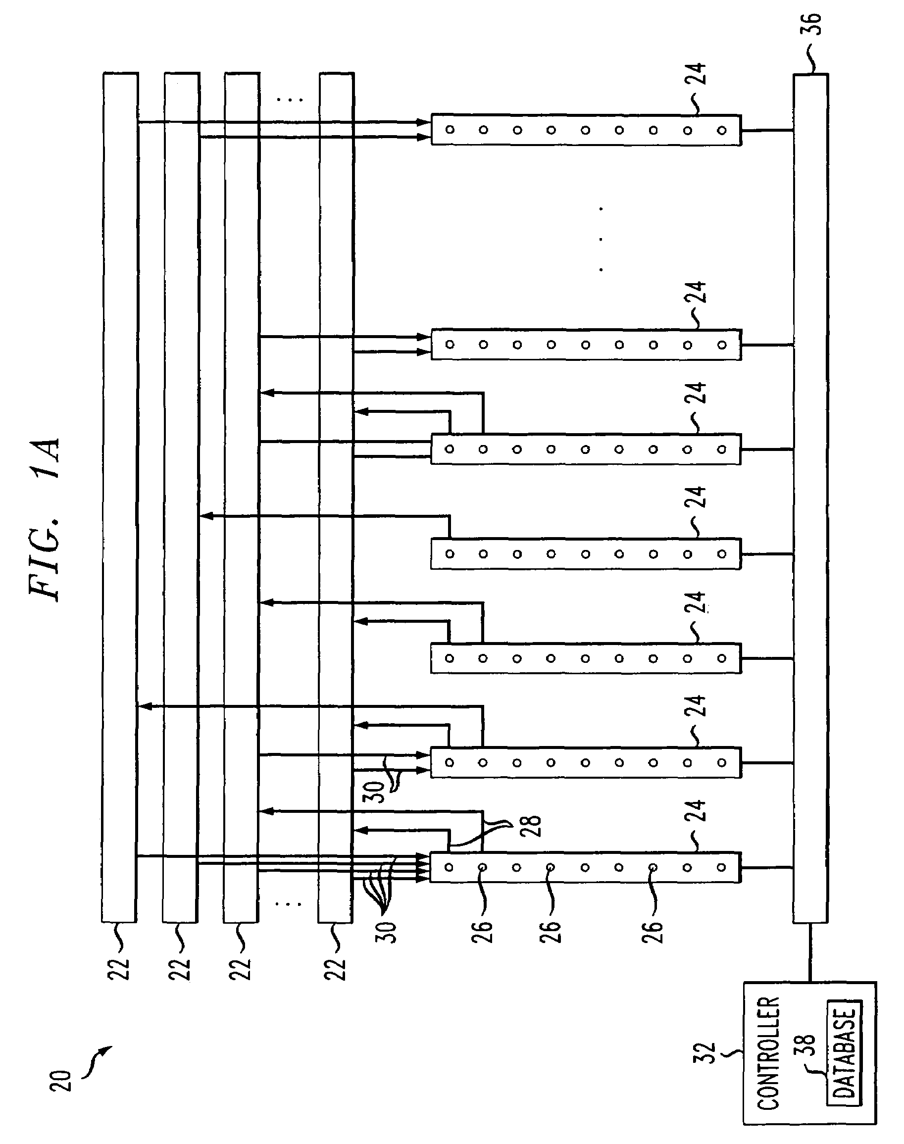
[0045]FIG. 1A is a schematic illustration of a modular switch 20, in accordance with a preferred embodiment of the present invention. Switch 20 comprises a plurality of cards 24 to which computers or other devices connect. Preferably, cards 24 comprise a plurality of ports 26 to which the computers connect. Switch 20 preferably also comprises a plurality of sub-buses 22 which are used for communication between cards 24. Preferably, each card 24 has a plurality of output links 28 which connect the card to the buses 22 to which it transmits. In addition, each card 24 preferably has a plurality of input links 30 with which card 24 listens to the sub-buses it is assigned to listen to.

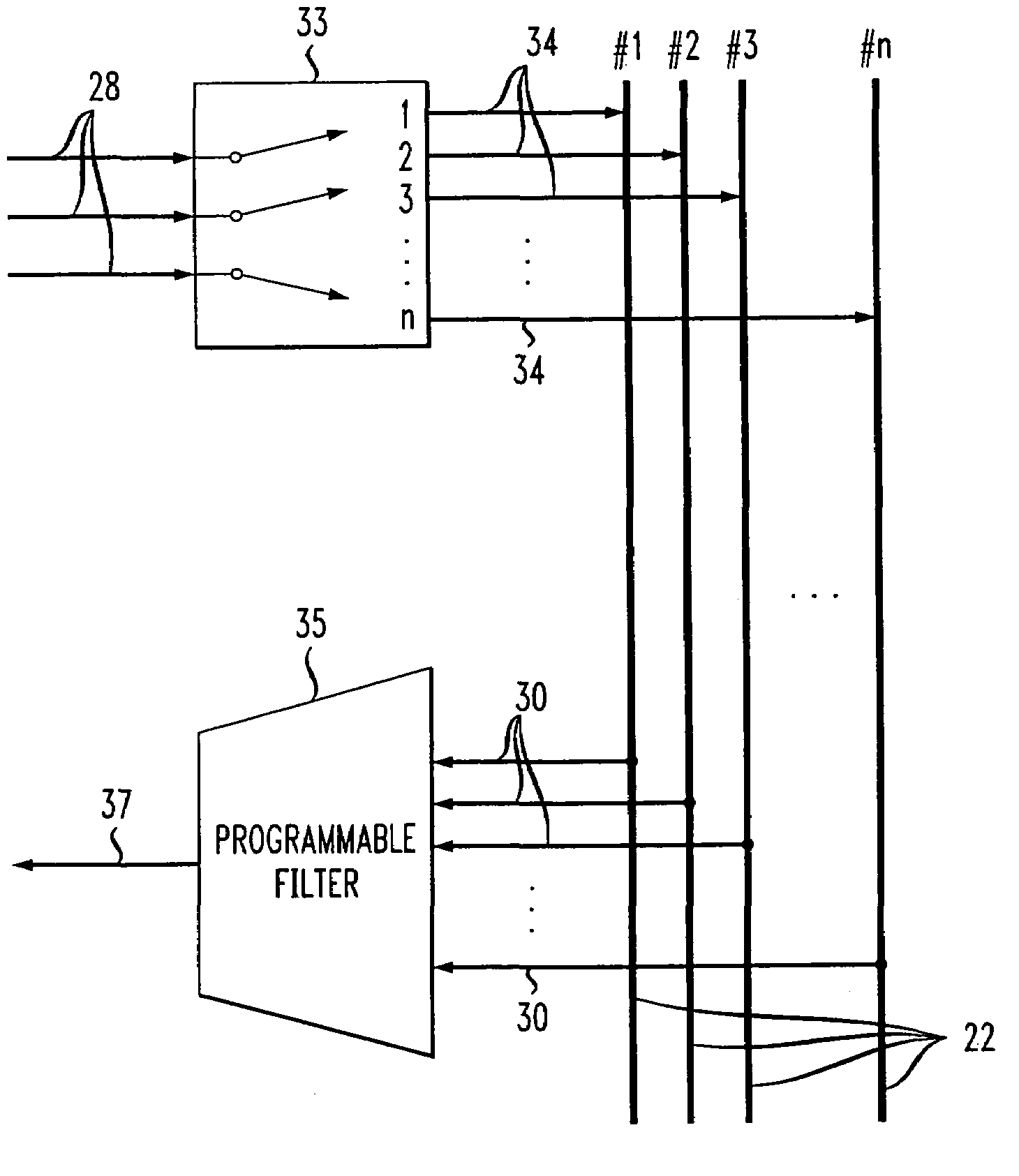
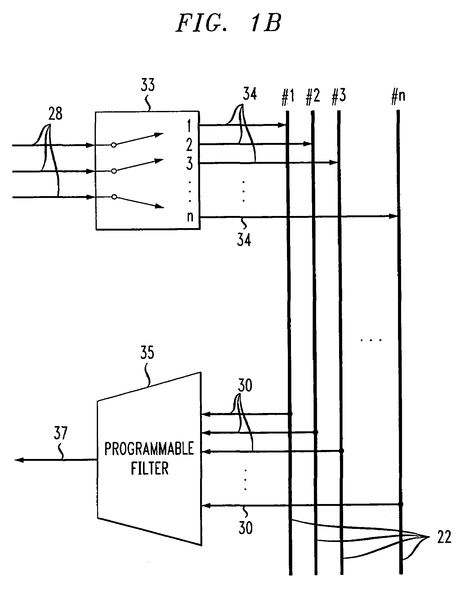
[0046]FIG. 1B is a schematic illustration of the connection between cards 24 and sub-busses 22 of modular switch 20, in accordance with a preferred embodiment of the present invention. Preferably, each card 24 has a predetermined number of links 28, e.g., three links, which are sufficient to allow the card ...


PUM


Abstract

A modular switch, comprising a plurality of backplane sub-buses; a plurality of cards which are each allocated one or more of the backplane sub-buses; and a controller which dynamically allocates the backplane sub-buses to the plurality of cards, based on the bandwidth needs of the cards. Preferably, the bandwidth capacity of substantially all the backplane sub-buses is less than the sum of the maximal transmission bandwidth capacities of the cards.

Description

FIELD OF THE INVENTION[0001]The present invention relates to communication networks and in particular to modular switches of local area networks.BACKGROUND OF THE INVENTION[0002]Many modular switches include a plurality of cards which are connected by a backbone bus with a limited bandwidth. Generally, a box of the modular switch comprises a plurality of slots for receiving cards, the slots being connected by the backbone bus.[0003]When the number of slots in the modular switch is relatively large and / or the amount of bandwidth needed by each card is large, the bandwidth of a bus which allows all the cards to transmit their entire capacity concurrently when all the slots are full with cards, may be very large. A bus with such a large bandwidth is very expensive and is not generally necessary as substantially nobody uses all the cards at maximal capacity at the same instant. Therefore, it is common to use a bus with a lower bandwidth. It is required, however, that the use of a lower ...

Claims


Application Information

Patent Timeline
IPC IPC(8): G06F13/40G08C15/00H03K19/007H04L12/56H04L12/44
CPCG06F13/409
Inventor YONA, NIRBEN MOSHE, YOSEFYITZHAKI, DORIFELDMAN, MICHAELNAVON, GIDISHIMONI, JACOB
Owner LUCENT TECH NETWORKS
Learn More