
Setting device of a force feedback type

a technology of force feedback and setting device, which is applied in the direction of mechanical control device, electric controller, domestic cooling device, etc., can solve the problems of not being able to recognize and hardly distinguish the sensations of the respective control item by the operator, and achieve the effect of reliable recognition

Inactive Publication Date: 2006-08-08
ALPS ALPINE CO LTD
View PDF10 Cites 4 Cited by
  • Summary
  • Abstract
  • Description
  • Claims
  • Application Information

AI Technical Summary

Benefits of technology

[0007]Accordingly, it is an object of the present invention to provide a setting device of a force feedback type that allows an operator to easily recognize which control item of an electronic device the operator is attempting to set by easy distinction of sensations provided by an operating unit of the setting device common to a plurality of control items.
[0009]In the above-described structure according to the present invention, a sensation provided by the setting unit when the operation of the setting unit is restricted is obviously different from a sensation when the operation of the setting unit is not restricted. Accordingly, the operator can easily recognize which control item the operator is setting.
[0011]In the above-described structure according to the present invention, a sensation provided by the setting unit during an airflow rate setting is reliably distinguished from a sensation provided by the setting unit during an air outlet setting. As a result, the operator can reliably recognize which one of airflow rate and air outlet the operator is attempting to set.
[0013]In the above-described structure according to the present invention, a sensation provided by the setting unit during a temperature setting is reliably distinguished from a sensation provided by the setting unit during an air outlet setting. As a result, the operator can reliably recognize which one of temperature and air outlet the operator is attempting to set.

Problems solved by technology

Therefore, in a situation where an operator cannot concentrate on a sensation provided by the rotary knob, as is the case where the operator operates the rotary knob while driving a car, the operator can hardly distinguish the sensations for the respective control items and cannot sometimes recognize which control item the operator is attempting to set, which is a problem.

Method used


Image

  • Setting device of a force feedback type
  • Setting device of a force feedback type
  • Setting device of a force feedback type

Examples


Embodiment Construction

[0020]An embodiment of an in-car setting device according to the present invention will now be described with reference to FIGS. 1 to 6.

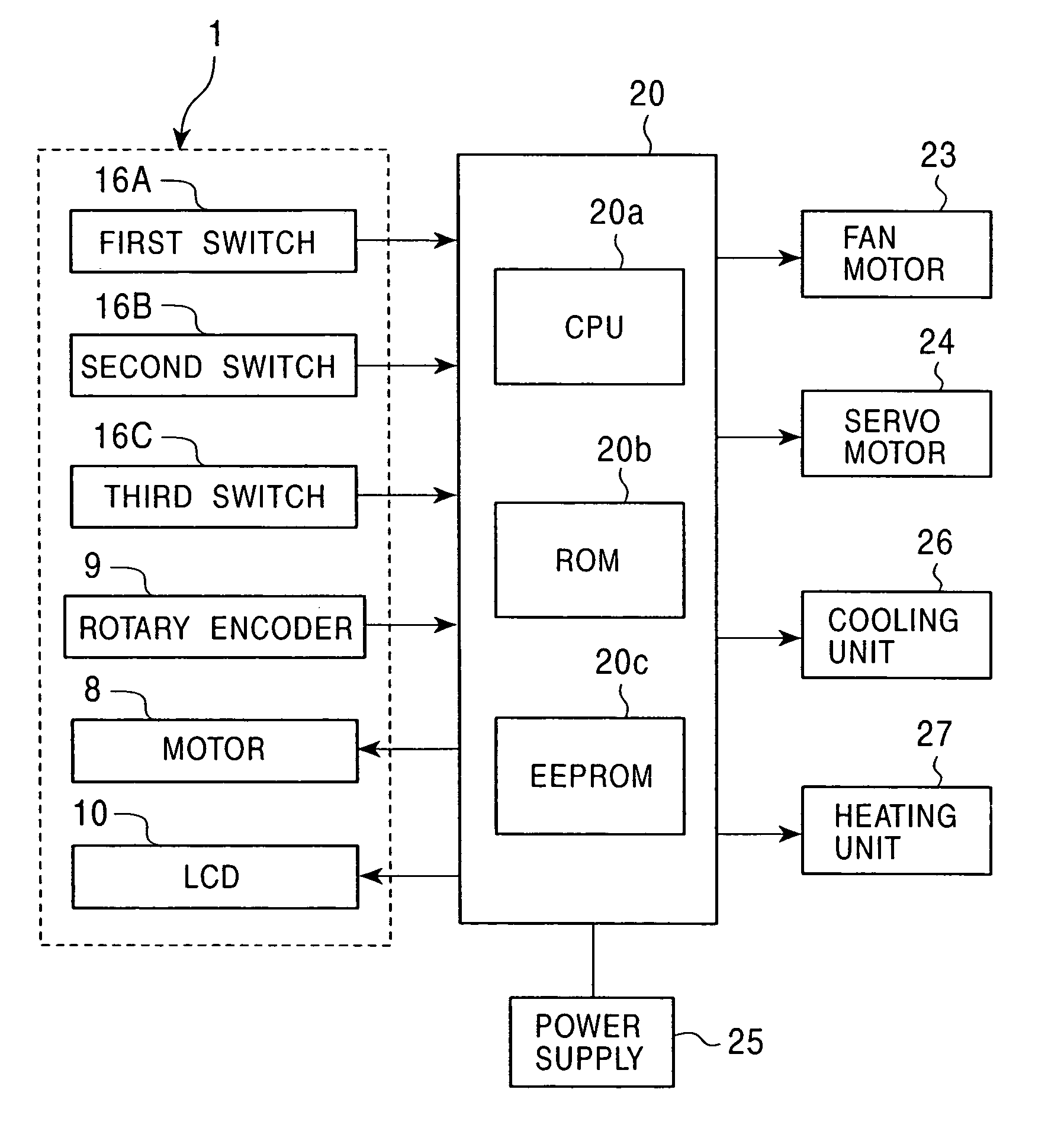
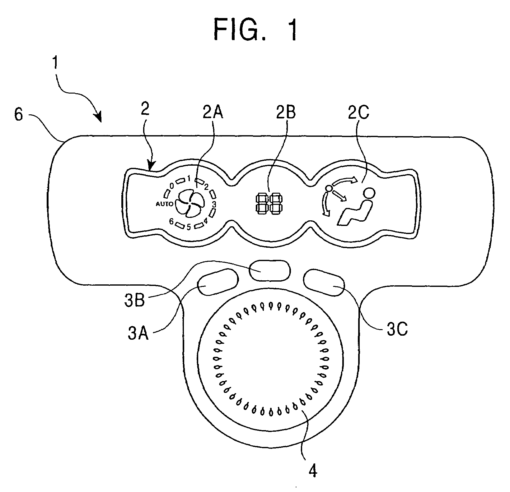
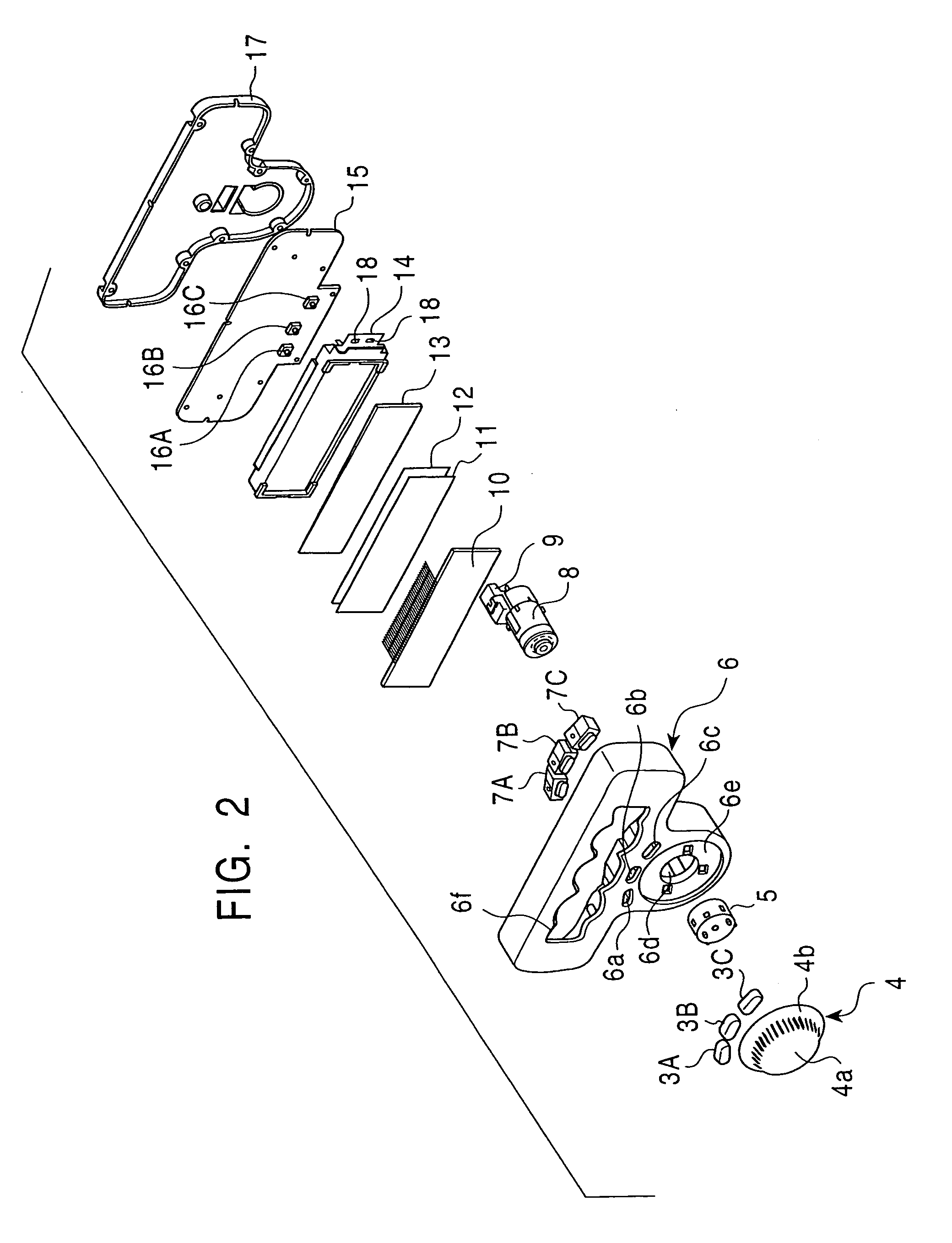
[0021]FIG. 1 is a front view of an operating device according to an embodiment of the present invention. FIG. 2 is an exploded perspective view of the operating device shown in FIG. 1. FIG. 3 is a block diagram of an electronic system according to the embodiment. FIG. 4 is a schematic diagram illustrating a force feedback pattern for an airflow rate setting of an automotive air conditioner according to the embodiment. FIG. 5 is a schematic diagram illustrating a force feedback pattern for a temperature setting of the automotive air conditioner according to the embodiment. FIG. 6 is a schematic diagram illustrating a force feedback pattern for an air outlet setting of the automotive air conditioner according to the embodiment.

[0022]In this embodiment, the device includes an operating unit 1. As shown in FIG. 1, the operating unit 1 includes a display...


PUM


Abstract

A setting device of a force feedback type has an operating unit commonly used to set a plurality of control items of an electronic device. To provide a different sensation to the operating unit depending on the control items, a force feedback pattern for an airflow rate setting is provided to a rotary knob, which is the operating unit, so that an operation of the rotary knob to rotate beyond an upper limit or a lower limit of an airflow rate range is restricted, and a force feedback pattern for the air outlet setting is provided to the rotary knob so that a rotational operation of the rotary knob is not restricted.

Description

[0001]This application claims the benefit of priority to Japanese Patent Application No. 2003-314117 filed on Sept. 5, 2003, herein incorporated by reference.BACKGROUND OF THE INVENTION[0002]1. Field of the Invention[0003]The present invention relates to a setting device of a force feedback type in which a plurality of control items of an electronic device are set through a single common operating unit. When one of the control items is set, a force feedback pattern which is inherent in the control item is provided to the operating unit so that an operator is made aware of the set control item by the sensation of operation of the operating unit. In particular, the present invention relates to a setting device of a force feedback type providing improved force feedback to an operating unit.[0004]2. Description of the Related Art[0005]Among in-car setting devices, such as automotive air conditioner setting devices, setting devices of a force feedback type are known. In the automotive ai...

Claims


Application Information

Patent Timeline
Patent Type & Authority Patents(United States)
IPC IPC(8): F25D17/00G05B11/01G09G5/00B60H1/00B60K20/02B60R16/02G05G5/03G06F3/023
CPCB60H1/0065G05G5/03B60H1/00985
Inventor SATO, HIROYUKIMURAKAMI, KAZUYUKIOIKAWA, TOMOHIROMIYASAKA, YASUHIRO
Owner ALPS ALPINE CO LTD
Learn More