
Parallel jaw locking toggle wrench/pliers with economic/ergonomic handles

a toggle wrench and wrench technology, applied in the field of adjustable locking pliers, can solve the problems of jaw slippage, difficulty in releasing the movable lower jaw member from the outer side edge length dimensions of the rectangularly shaped support member, and not providing adjustable toggles, etc., to achieve convenient grip, mechanical leverage advantages, and convenient use

Inactive Publication Date: 2006-08-08
TORTOLANI KENNETH GUY
View PDF105 Cites 27 Cited by
  • Summary
  • Abstract
  • Description
  • Claims
  • Application Information

AI Technical Summary

Benefits of technology

[0022]As defined by the above-identified Invention: To provide locking pliers with jaw members having an adjustable parallel relationship - applying a symmetrical clamping force across the surface area of the object (or objects) being clamped; including having mechanical leverage advantages by locating a movable upper handle pivoting over a lower fixed handle; and including having ease of use advantages of presetting the clamping force to be applied - by having one of the two toggle angle positioning apparatus located in the movable upper ha

Problems solved by technology

This binding pressure makes releasing the movable lower jaw member from the outer side edge length dimensions of the rectangularly shaped support member difficult during the release of clamping pressure from the clamped object.
In contemplation of the Specification, the prior art has not provided adjustable toggle locking pliers embodying parallel opposing jaw members utilizing a substantially rectangular shape support member section with mechanisms of releasing clamping pressure more closely resembling the release of clamping pressure employed by conventional toggle locking pliers.
(a) Jaw members not in parallel relationship - resulting in jaw slippage from less surface area contact with object (or objects) being clamped.
(b) Width adjustment between handles (toggle angle adjustment) being difficult to determine and keep secured during clamping / releasing procedure - resulting in an awkward over adjustment and subsequent readjustment of adjustment screw and / or toggle stop screw.
(b) Handle construction being not of ergonomic / economic design - results in awkwardness during handle operation by the reduction of hand grip.
(3) Disadvantages of Parallel Action Toggle Wrenches:
(a) Handle construction being not of ergonomic / economic design - results in awkwardness during handle operation by the reduction of hand grip.
(b) Toggle release lever upper handle design being partially housed slidable in a lower handle design - results in awkwardness during the clamping / releasing procedure from the subsequent increased lower handle width dimension (width dimension measured from either top or bottom view).
(c) Lower handle design having an externally mounted toggle adjustment assembly - results in uncomfortableness during handle operation by the reduction of hand grip.
(d) Movable lower jaw member design has rigidly mountable parallel opposing structures slidable and binding along parallel opposing side edge lengthwise dimensions of a rectangularly shaped support member.
The disadvantages of conventional and / or parallel locking pliers are the difficulty in determining the readjustment of the locking toggle before different size objects are clamped; and cost of manufacture.
(a) The awkward release of the locking mechanism.
(b) The awkward position of the locking mechanism when in the unlocked mode.
(c) Jaw members being not parallel when clamped.

Method used


Image

  • Parallel jaw locking toggle wrench/pliers with economic/ergonomic handles
  • Parallel jaw locking toggle wrench/pliers with economic/ergonomic handles
  • Parallel jaw locking toggle wrench/pliers with economic/ergonomic handles

Examples


Embodiment Construction

[0315]Description of the preferred embodiments:

[0316]As defined in this specification; part fabrication of the above - identified Invention is as follows:

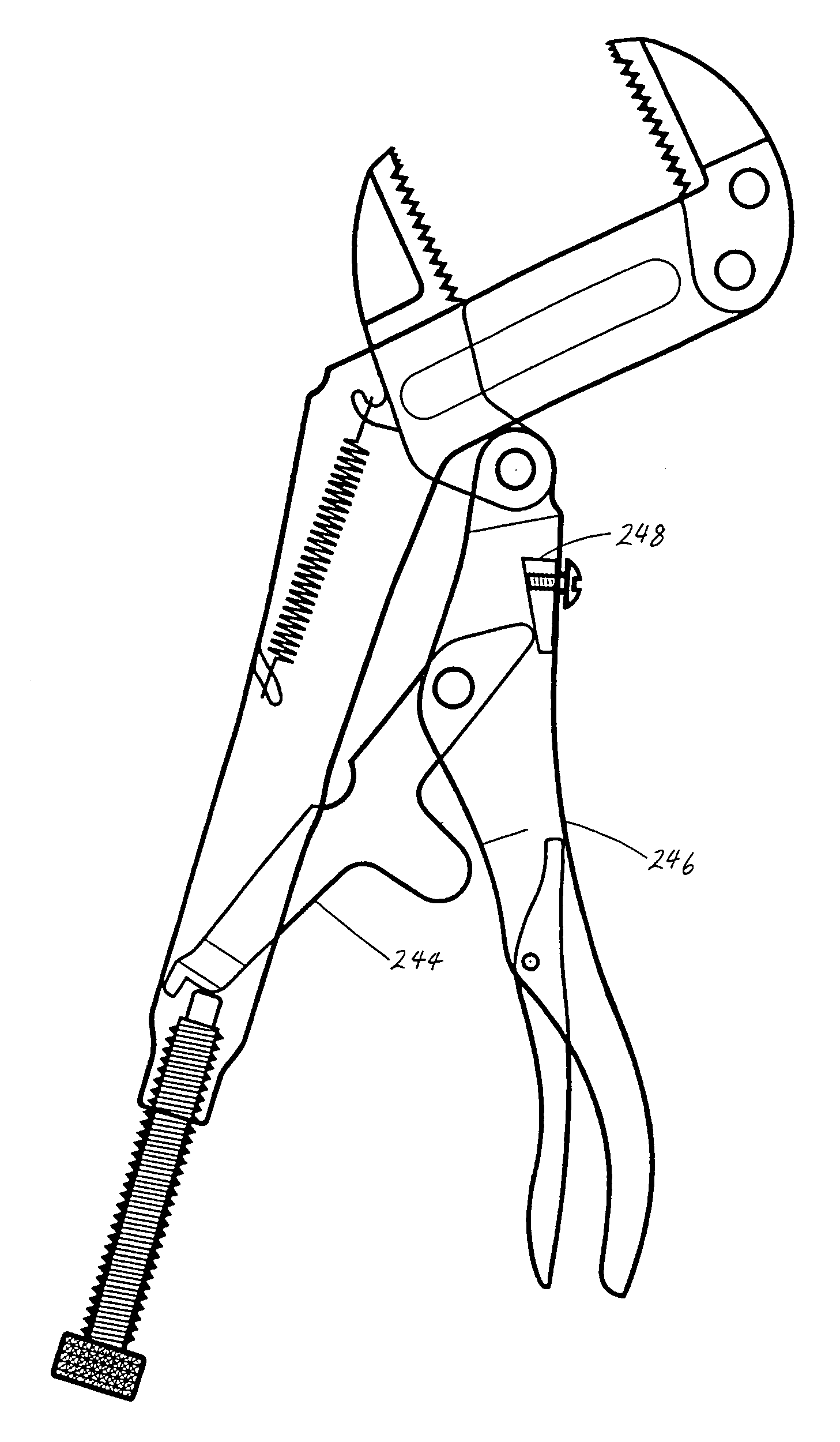
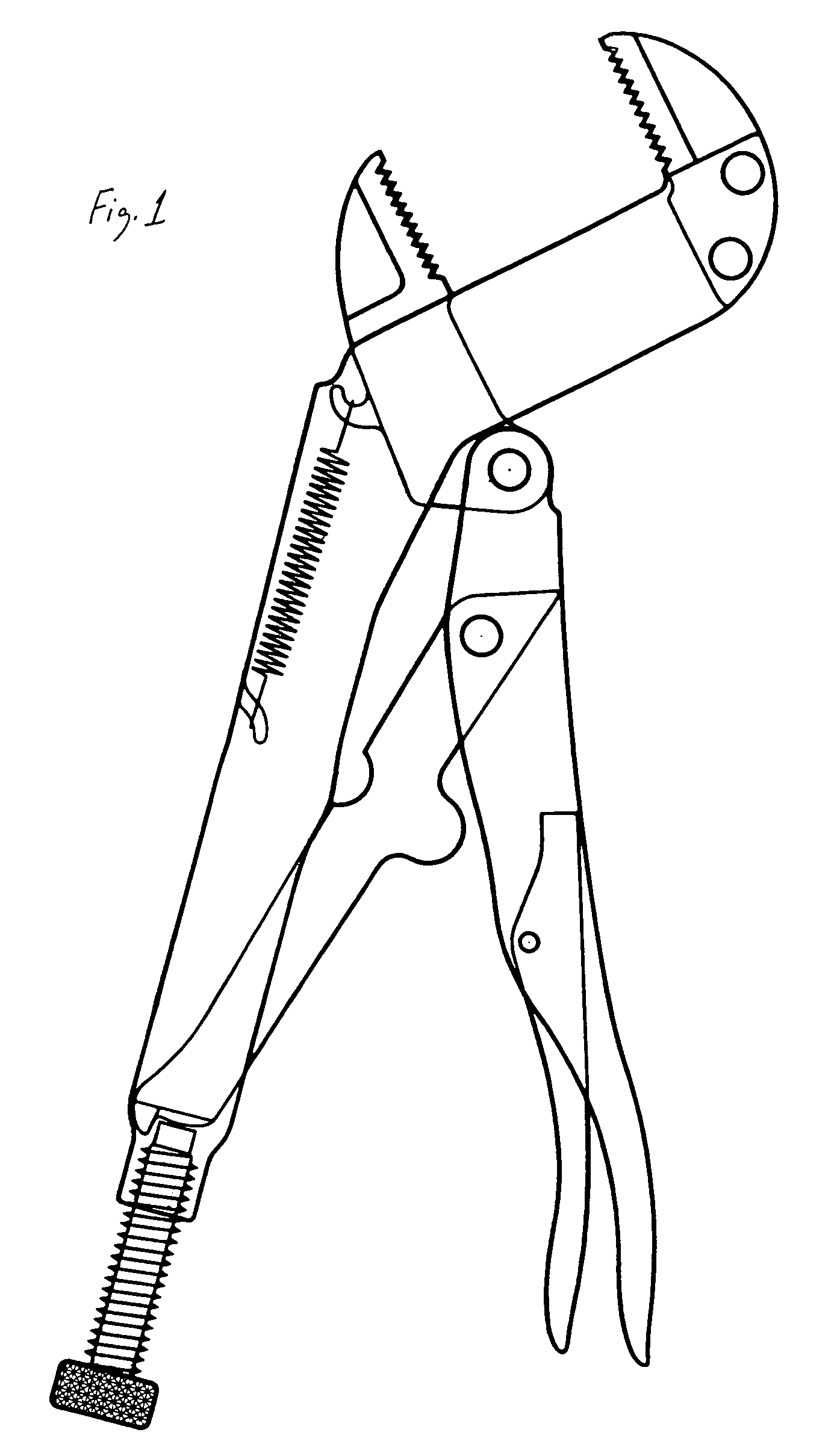
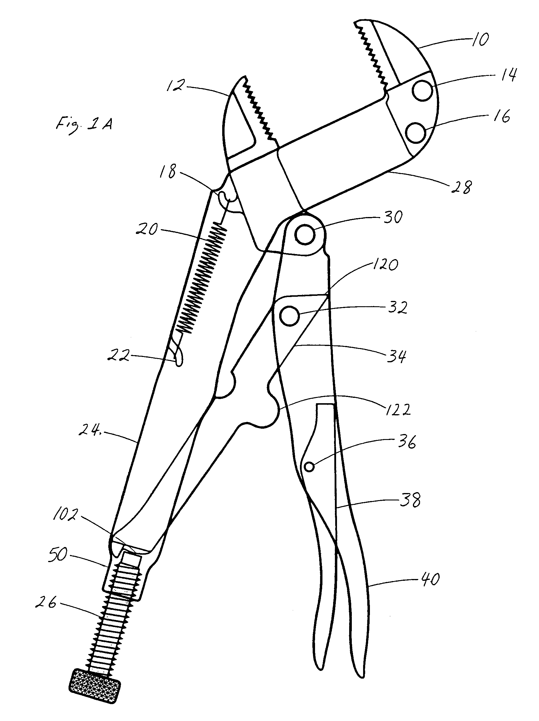
[0317]FIG. 1 and FIG. 1A depict the working relationship of mechanisms (some details not shown) being under spring tension - with jaw members in the fully open position.

[0318]FIG. 2 is a cross-section of lower handle 24: Other cross-section of lower handle 24 is not shown. Both cross-sections of lower handle 24 have the same dimensions. Rivet holes 42 and 44 depicted in the specification, are formed into lower handle 24 by a pressing / shearing process or by drilling (or by mechanism known in the art). Hook 22 is formed by a pressing / shearing process (or by mechanism known in the art). In the rear housing; threads 46 are formed by a tapping procedure (or by mechanism known in the art) after (or during) the forming of rear channel 48 of lower handle 24.

[0319]The outer dimensions of lower handle 24 are formed into a flat pattern by a p...


PUM


Abstract

“Parallel Jaw Locking Toggle Wrench / Pliers with Economic / Ergonomic Handles” comprising: a fixed jaw member being in parallel relationship to a slidable jaw member; the fixed jaw member constructed (by riveting or welding means) to support member - the support members being formed integral to a lower handle; the slidable jaw member slidably contiguous to said support member; the slidable jaw member pivotably attachable (by riveting) to a rotatable upper handle opposing said lower handle; a spring tensioned to said slidable jaw member - with the spring attachable to said lower handle; the spring allowing for the operation of said slidable jaw member, a toggle, said upper handle, and an adjustment screw; the toggle pivotably attachable (by riveting) to said upper handle; the toggle pivotably contacting said adjustment screw; the adjustment screw rotatably mounted in said lower handle; a release lever levered off of said toggle; the release lever pivotably attachable (housed) in said upper handle; and a compound toggle link means levered off of said toggle as an alternate design to said release lever.

Description

CROSS-REFERENCE TO RELATED APPLICATIONS[0001]This is a Continuation-In-Part Application of my earlier filed nonprovisional application: “PARALLEL JAW LOCKING TOGGLE PLIERS / WRENCH WITH ERGONOMIC / ECONOMIC HANDLES”—Appn. No. 10 / 034,684—Filing Date Dec. 28, 2001, now abandoned; and discloses information contained in my earlier filed nonprovisional application “PARALLEL JAW LOCKING PLIERS WITH MODIFIED ERGONOMIC / ECONOMIC HANDLES”—Appn. No. 09 / 654,870—Filing Date Sep. 1, 2000, now abandoned; and discloses information contained in my earlier filed provisional applications: “PARALLEL JAW LOCKING PLIERS”—Appn. No. 60 / 138,571—Filing Date Jun. 11, 1999 and “PARALLEL JAW LOCKING PLIERS WITH ERGONOMIC HANDLES”—Appn. No. 60 / 267,914—Filing Date—02 / 06 / 2001; and also discloses information contained in my earlier filed nonprovisional application: “AUTOMATIC SELF-SIZING PARALLEL JAW LOCKING PLIERS”—Appn. No. 09 / 200,189—Filing Date Nov. 25, 1998, now-abandoned.FEDERALLY SPONSORED RESEARCH[0002]Not Appl...

Claims


Application Information

Patent Timeline
IPC IPC(8): B25B7/12
CPCB25B7/123B25B7/10
Inventor TORTOLANI, KENNETH GUY
Owner TORTOLANI KENNETH GUY
Learn More