Pneumatic tire having a stabilizing system for under-inflated conditions

a technology of pneumatic tires and stabilizing systems, which is applied to inflatable tires, vehicle components, wheels, etc., can solve the problems of unsafe and damaging situations, damage to tires, and/or vehicle movement in an uncontrolled manner, and achieve the effect of not significantly increasing the mass of tires

Inactive Publication Date: 2006-08-08
BRIDGESTONE FIRESTONE NORTH AMERICAN TIRE
View PDF24 Cites 7 Cited by
  • Summary
  • Abstract
  • Description
  • Claims
  • Application Information

AI Technical Summary

Benefits of technology

[0005]The present invention provides a stabilizing system that allows a tire / wheel assembly to have improved run flat characteristics without adding unduly excessive mass, without complicating manufacturing procedures, and / or without requiring the mounting of extra structural pieces on the rim or tire.
[0008]The projections and grooves of the stabilizing system add only a minimal amount of mass to the tire whereby the mass of the tire is not significantly increased, a significant factor for automobile construction in terms of rolling resistance of the tire and total weight of the automobile. Also, the projections and the grooves can be formed during the curing stage of the tire-making process whereby extra steps are not added to the tire manufacturing procedure. Furthermore, the stabilizing system of the present invention does not require the mounting of any structural components on the rim and / or within any of the tire portions.

Problems solved by technology

Specifically, the ground-engaging portion of the tire is not held sufficiently rigid and “wobbles” during the flat tire driving period and the deflated tire actually rides on its collapsed sidewall portions.
This can result in destruction of the tire and / or the vehicle moving in an uncontrolled manner out of the prescribed direction of travel under the influence of forces brought about by the under-inflated condition of the tire.
In the extreme, the tire can separate from the wheel, causing the driver to attempt to operate the vehicle by driving on the metal rim, a very unsafe and damaging situation.
While such techniques can improve run flat characteristics, they tend to add a significant amount of excess mass, complicate manufacturing procedures and / or require the mounting of extra structural pieces on the rim or within the tire.

Method used


Image

  • Pneumatic tire having a stabilizing system for under-inflated conditions
  • Pneumatic tire having a stabilizing system for under-inflated conditions

Examples


Embodiment Construction

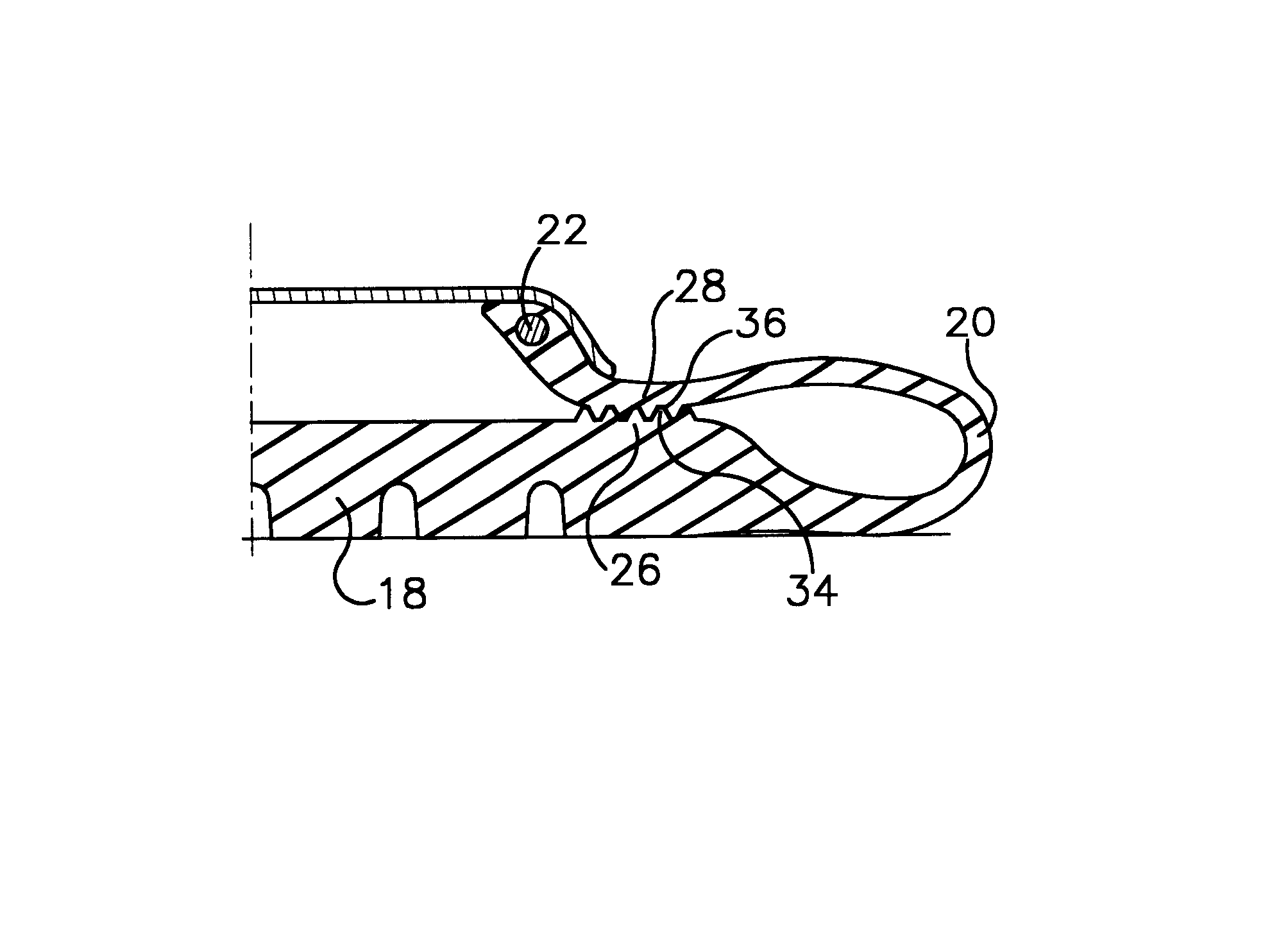
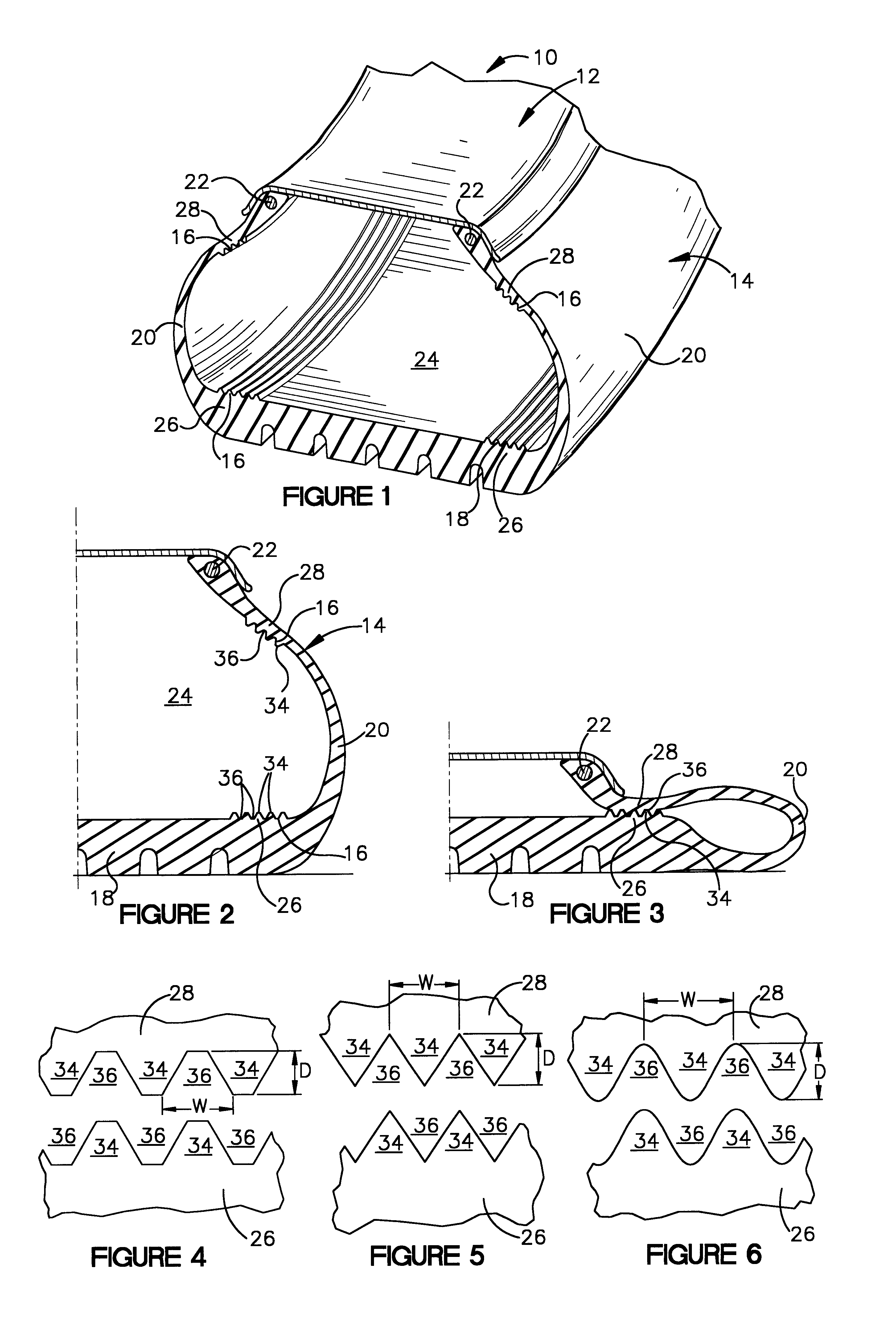
[0016]Referring now to the drawings in detail, and initially to FIG. 1, a tire and wheel assembly 10 according to the present invention is shown. The tire and wheel assembly 10 comprises a rim 12 and pneumatic tire 14 mounted on the rim 12. A stabilizing system 16 is incorporated into the assembly 10, and particularly the tire 14, to provide the tire / wheel assembly 10 with improved run flat characteristics. As is explained in more detail below, this improvement is accomplished without adding unduly excessive mass, without significantly complicating manufacturing procedures, and / or without requiring the mounting of extra structural pieces on the rim 12 or tire 14.

[0017]The tire 14 comprises a ground-engaging portion 18 and a pair of sidewall portions 20 that terminate in a pair of bead portions 22. The portions 18 and 20 define an inflation chamber 24 which, in the illustrated embodiment, is free from intermediate supporting structure. The portions can each be viewed as including int...


PUM


Abstract

A stabilizing system for a pneumatic tire and wheel assembly includes complimentary projections and grooves on internal regions of the tire which contact each during an under-inflated condition. The projections and grooves mate with each other during the under-inflated condition to provide mechanical and positive interconnection between the regions in a direction of travel thereby inhibiting lateral movement between the tire and the rim.

Description

FIELD OF THE INVENTION[0001]The present invention relates to a pneumatic tire having a stabilizing system for improving run flat characteristics during under-inflated conditions.BACKGROUND OF THE INVENTION[0002]A tire and wheel assembly commonly comprises a rim and a pneumatic tire mounted to the rim. The pneumatic tire typically includes a ground-supporting portion and a pair of sidewall portions which define an inflation chamber. If, for example, the inflation chamber is free from intermediate supporting structure, regions of the sidewall portions will collapse into each other when the tire becomes deflated or in an otherwise under-inflated condition. This will result in internal tread-adjacent regions contacting internal rim-adjacent regions during an under-inflated condition. The tread-adjacent region is usually just radially inward of the tire's tread edge and the rim-adjacent region is usually just radially outward of the rim.[0003]In the event of an under-inflated condition, ...

Claims


Application Information

Patent Timeline
Patent Type & Authority Patents(United States)
IPC IPC(8): B60C17/00B60C17/10B60C3/00B60C13/02B60C17/08
CPCB60C13/02B60C17/00B60C17/08B60C17/10B60C17/009B60C17/047B60C13/004Y10T152/10117B60C2013/026
Inventor VOSSBERG, STEPHEN M.
Owner BRIDGESTONE FIRESTONE NORTH AMERICAN TIRE
Why Eureka
Try Eureka