
Locking system for catheter

a locking device and catheter technology, applied in the field of catheters, can solve the problems of difficult insertion of catheter tubes into blood vessels, and achieve the effect of easy release of the locked position of the locking device, easy insertion into the body cavity, and easy insertion

Inactive Publication Date: 2006-08-08
LEE NAK HO
View PDF16 Cites 33 Cited by
  • Summary
  • Abstract
  • Description
  • Claims
  • Application Information

AI Technical Summary

Benefits of technology

"The present invention is a drainage catheter with a locking device that solves problems in the related art. The locking device can easily form the distal end of the catheter tube into the desired configuration, prevent the loop configuration of the distal end from being inadvertently released during operation, and easily release a locked position of the locking device. The catheter is also easy to insert into a body cavity. The hub has a guide hole and a first body passage that communicates with the guide hole. The tip of the tubular member has a double adhesion structure."

Problems solved by technology

In addition, because a tip of the catheter tube is made of flexible (or soft) material such as polyamide, it is difficult to insert the catheter tube into a blood vessel.

Method used


Image

  • Locking system for catheter
  • Locking system for catheter
  • Locking system for catheter

Examples


Embodiment Construction

[0016]Reference will now be made in detail to the preferred embodiments of the present invention, examples of which are illustrated in the accompanying drawings.

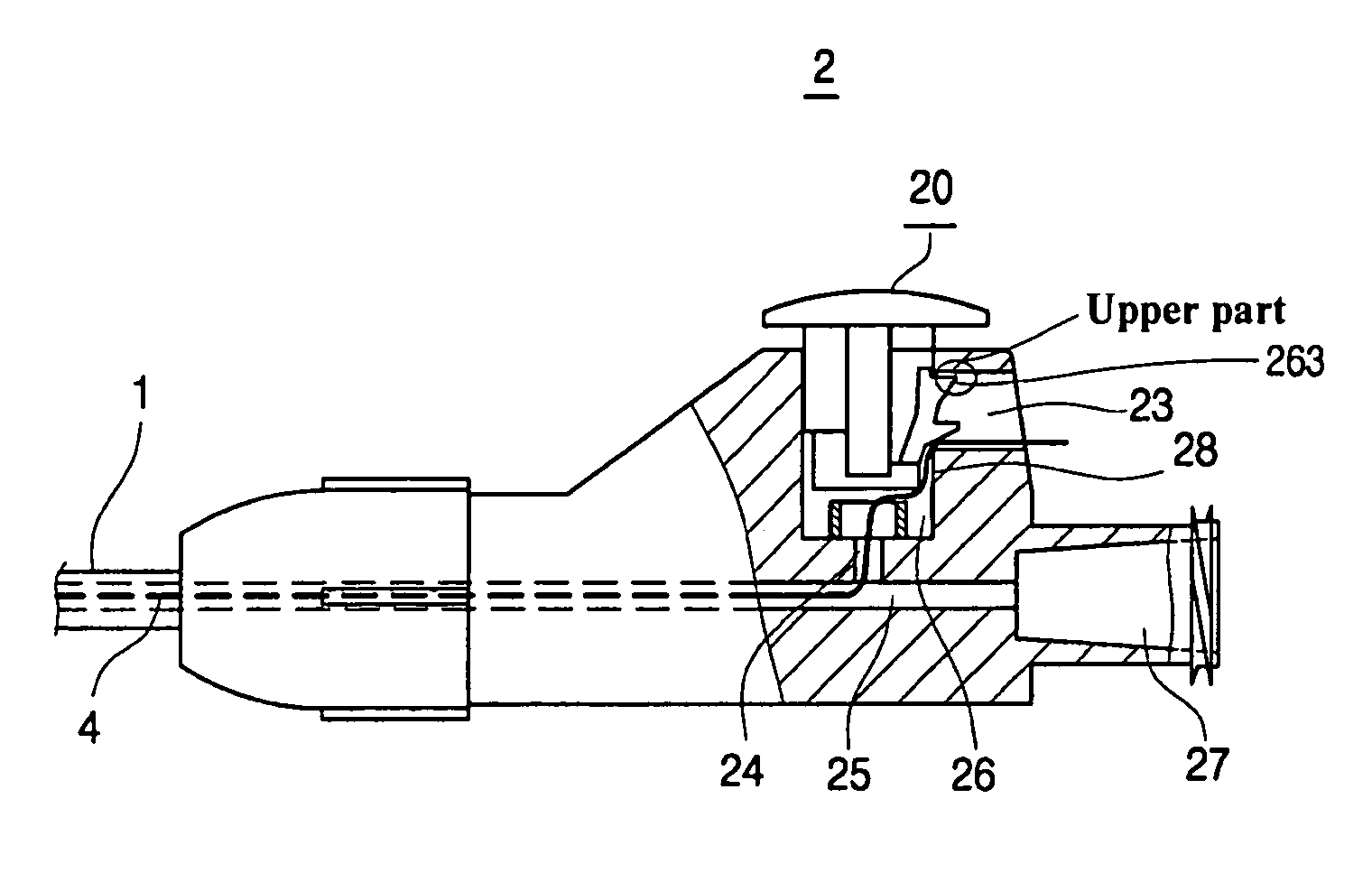
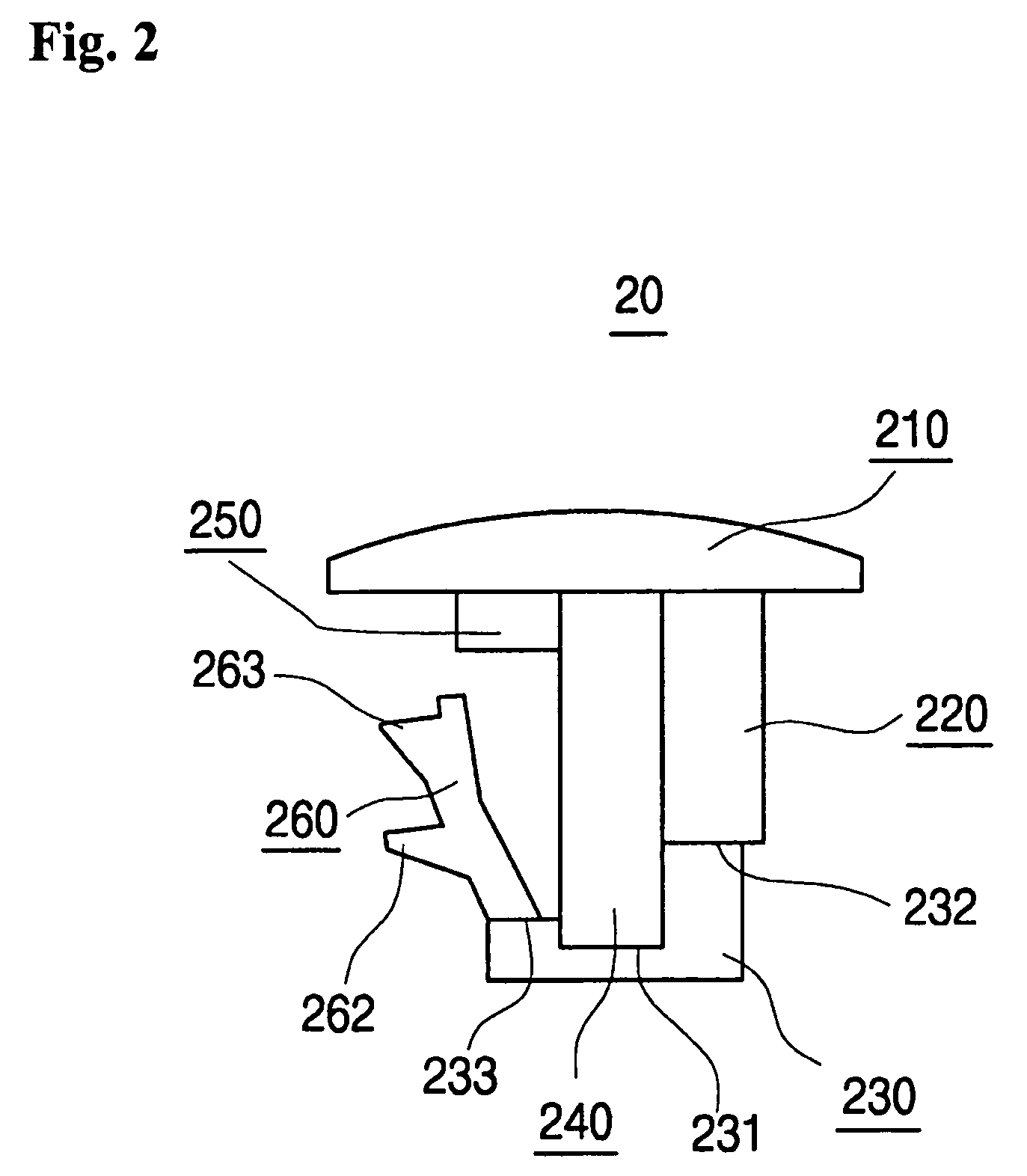
[0017]Referring to FIG. 2, a locking device of the present invention comprises a semi oval button (210). The button is coupled to a main operating part (240) with a rectangular shape. On the right side of the main operating part (240), a sub-operating part (220) is positioned alongside of the main operating part. On the left side of the main operating part (240), an arrival guide part (250) about ⅙ in length of the main operating part (240) is positioned alongside of the main operating part. The distal end of the main operating part (240) is inserted into an accepting hole (231) of an accepting part (230). The accepting part (230) has a pair of projections (232 and 233) at both sides, one of which is longer than the other one. The top of the longer projection (232) is in contact with the bottom of the sub-operating part (220...


PUM

PropertyMeasurementUnit
shapeaaaaaaaaaa
angleaaaaaaaaaa
tensionaaaaaaaaaa

Abstract

A catheter of the present invention includes a tubular member and a lockable connector having a hub and a locking device. The locking device includes a semi-oval button; a rectangular main operating part; an accepting part having a pair of projections and an accepting hole; and a latching part coupled to one of the projections. The hub includes a guide hole into which the locking device is inserted and a first body passage formed horizontally toward the inside of the hub, the first body passage communicating with the guide hole. The locking device can be released from the locked position only by use of an appropriate key. A tip of the tubular member is made of hard material and has a double adhesion structure so that the catheter tube can easily be inserted into a body cavity.

Description

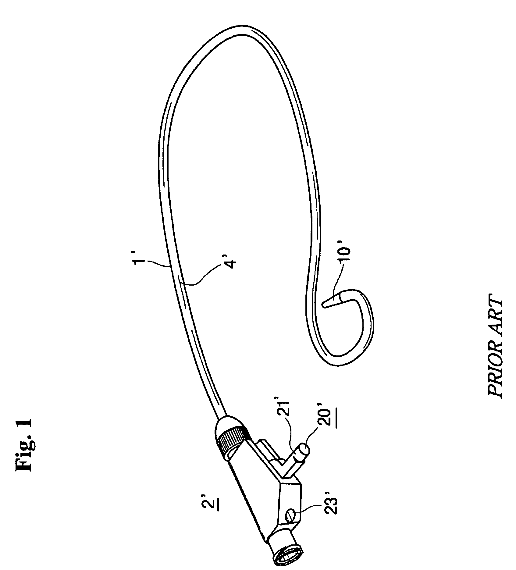
TECHNICAL FIELD[0001]The present invention relates to catheters and, more particularly, to a drainage catheter having a locking device which can be locked or unlocked more easily. In addition, the present invention relates to a distal end of catheter made of hard material so that the drainage catheter can easily be inserted into a body cavity.BACKGROUND ART[0002]Drainage catheters are generally used to drain bile or pus from a body cavity, for example, an abdominal cavity in order to mitigate symptoms of diseases. A Drainage catheter comprises a tubular member having a proximal end opposite a distal end, a tension member, and a lockable connector. The tubular member includes a series of holes positioned proximate the distal end. The distal end of the tubular member is formed to be positioned into a desired configuration such as a closed loop or pigtail. The tension member extends through the hollow tubular member and is positioned for drawing the distal end into the desired configur...

Claims


Application Information

Patent Timeline
Patent Type & Authority Patents(United States)
IPC IPC(8): A61M37/00A61M1/00A61L29/00A61M25/00A61M25/01A61M27/00A61M39/00
CPCA61M25/0097A61M25/0147A61M2025/09125A61M2025/0163
Inventor LEE, NAK-HO
Owner LEE NAK HO
Learn More