Artificial knee joint having a minimum knee angle

a knee joint and knee angle technology, applied in the field of artificial knee joints, can solve problems such as user falling down, and achieve the effect of preventing user falling down

Inactive Publication Date: 2006-08-08
CHEN SEN JUNG
View PDF6 Cites 52 Cited by
  • Summary
  • Abstract
  • Description
  • Claims
  • Application Information

AI Technical Summary

Benefits of technology

[0005]The object of this invention is to provide an artificial knee joint that can prevent the user from falling down when instantly shifting his or her center of gravity rearwardly and downwardly at the start of a downward slope.
[0006]According to this invention, an artificial knee joint includes a knee seat attached to a residual thigh, a support frame attached to a prosthetic lower leg, and a driving member disposed pivotally in a mounting recess in the knee seat. A cushion device is disposed between the knee seat and the driving member. Two links have lower ends connected pivotally to the support frame. Two pivot pins extend respectively through upper ends of the links, and are journalled respectively within two moun

Problems solved by technology

If this occurs, it is possible for the piston rod 12 to be moved instantly and rap

Method used


Image

  • Artificial knee joint having a minimum knee angle
  • Artificial knee joint having a minimum knee angle
  • Artificial knee joint having a minimum knee angle

Examples


Embodiment Construction

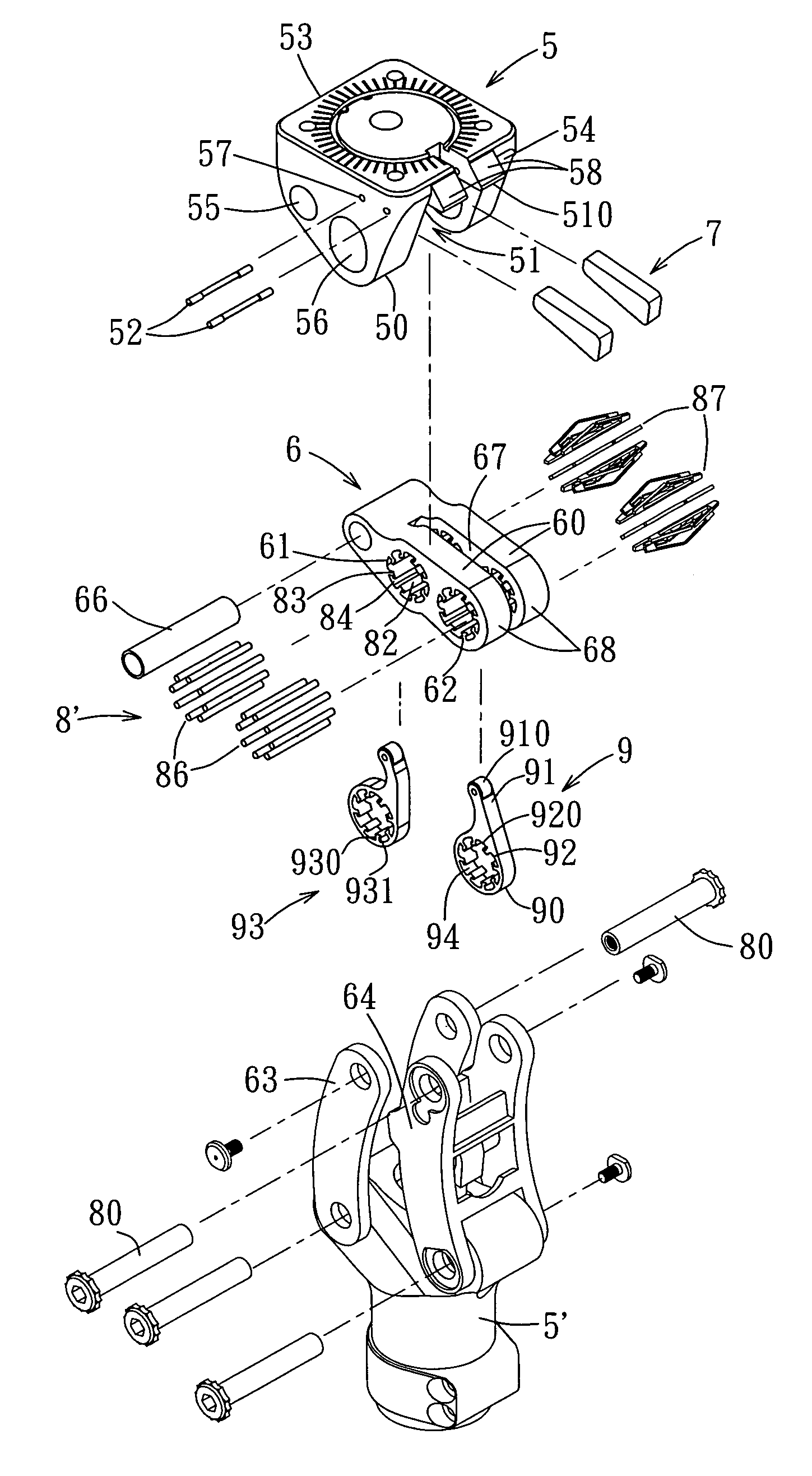
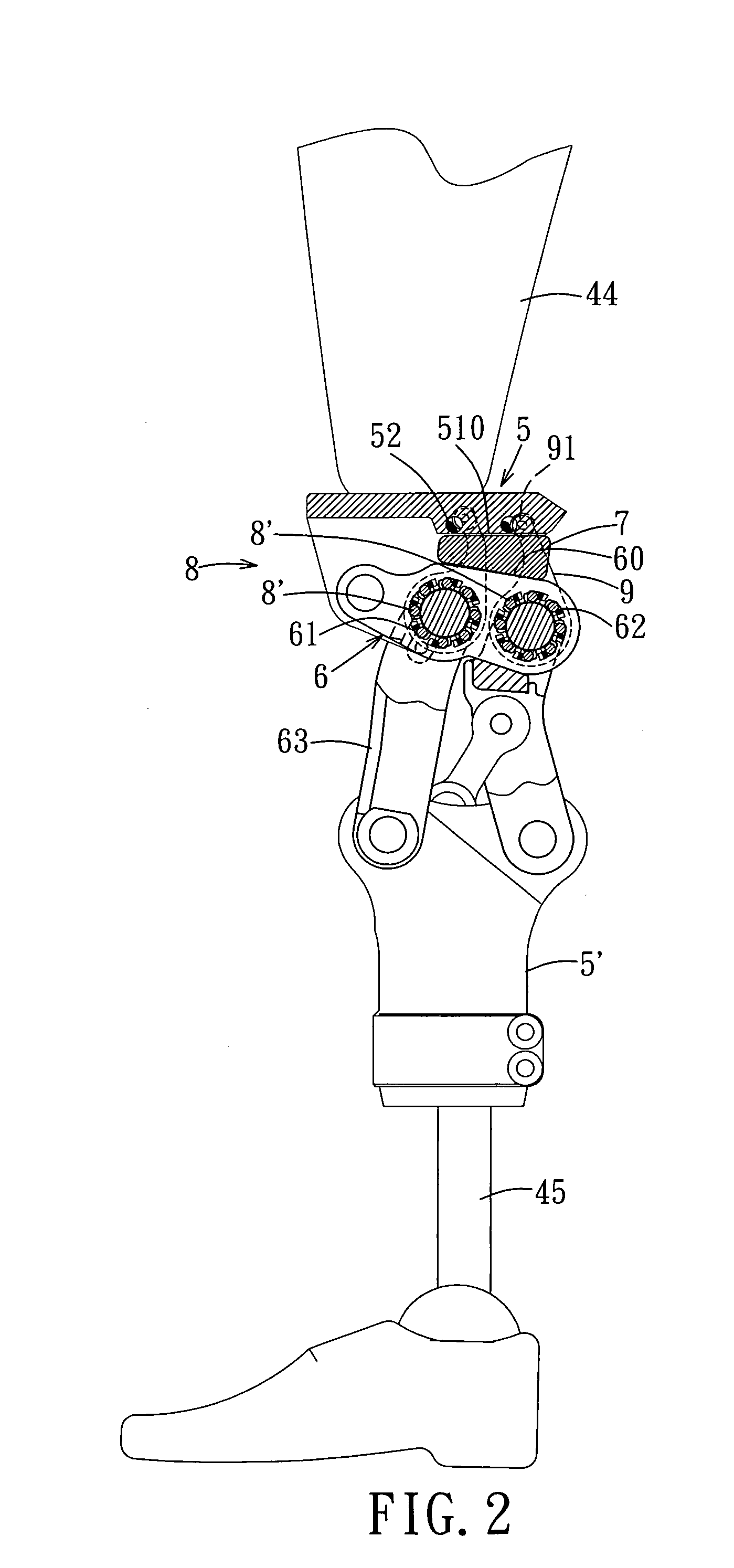
[0022]Referring to FIGS. 2, 3, 4, and 5, the preferred embodiment of an artificial knee joint according to this invention is adapted to interconnect a residual thigh 44 and a prosthetic lower leg 45. The artificial knee joint includes a knee seat 5 attached to the thigh 44, a support frame 5′ attached to the prosthetic lower leg 45, a driving member 6, two links 63, 64, a cushion device consisting of two rubber blocks 7, a bearing unit 8 consisting of two bearing members in the form of unidirectional bearings 8′, and two pin-locking members 9.

[0023]The knee seat 5 has a bottom end 50 that is formed with a mounting recess 51. The mounting recess 51 has a top end that is defined by an inner wall surface 510. Two stop members 52 are disposed respectively and fixedly within two parallel holes 57 in the knee seat 5, and extend through an upper end portion of the mounting recess 51. The knee seat 5 further has two opposite side surfaces 53, 54, two pivot holes 55, 56 formed through the kn...


PUM


Abstract

An artificial knee joint includes a knee seat attached to a residual thigh, a support frame attached to a prosthetic lower leg, and a driving member disposed pivotally in a mounting recess in the knee seat. A cushion device is disposed between the knee seat and the driving member. Two links have lower ends connected pivotally to the support frame. Two pivot pins extend respectively through upper ends of the links, and are journalled respectively within two mounting holes in the driving member by two bearing members, at least one of which is configured as a unidirectional bearing. When a knee angle is equal to a threshold angle, a pin-locking member is disposed in a pin-locking position so as to prevent rotation of the pivot pins within the driving member and, thus, relative rotation between the knee seat and the support frame.

Description

BACKGROUND OF THE INVENTION[0001]1. Field of the Invention[0002]This invention relates to an artificial knee joint, and more particularly to an artificial knee joint having a knee angle that is formed between a residual thigh and a prosthetic lower leg and that is no smaller than a threshold angle.[0003]2. Description of the Related Art[0004]Referring to FIG. 1, a conventional artificial knee joint includes a linkage 10, a knee seat 11 connected to a residual thigh, and a pneumatic cylinder for dampening downward movement of the knee seat 11. The pneumatic cylinder includes a piston rod 12 and a cylinder body 13 connected to a prosthetic lower leg. When the user walks down a slope, the center of gravity of the user may move rearwardly and downwardly within a very short time. If this occurs, it is possible for the piston rod 12 to be moved instantly and rapidly relative to the cylinder body 13, which may results in the user falling down.SUMMARY OF THE INVENTION[0005]The object of thi...

Claims


Application Information

Patent Timeline
IPC IPC(8): A61F2/68
CPCA61F2/644A61F2/76A61F2002/507A61F2002/5009
Inventor CHEN, SEN-JUNG
Owner CHEN SEN JUNG
Why Eureka
Try Eureka