Energy absorbent laminate

a technology of energy absorption and laminate, applied in the field of composite materials, can solve the problems of low stress resistance of bolted and riveted joints in composite materials, no relief from elastic stress concentration, and relatively brittleness of fiber-reinforced composite materials compared to conventional ductile metal alloys, etc., to achieve greater elongation, improve shearout, cutting and impact resistance, and improve the effect of strength

Inactive Publication Date: 2006-08-08
SAINT GOBAIN TECHN FABRICS CANADA +1
View PDF24 Cites 50 Cited by
  • Summary
  • Abstract
  • Description
  • Claims
  • Application Information

AI Technical Summary

Benefits of technology

[0008]Multi-layered composites useful in high loading applications are provided by this invention. In a first preferred embodiment of a mechanically fastened composite joint of this invention, a substrate and a multi-layered composite are provided. The composite includes a pair of resin-impregnated, fiber-containing layers. The composite further includes a fiber-containing core layer having a lower tensile modulus, higher toughness, and / or higher elongation at break than the resin impregnated, fiber-containing layers. The core layer is sandwiched between the pair of resin-impregnated, fiber-containing layers. Upon subjecting this composite to high external forces, the resulting composite joint has improved shearout, cutting and impact resistence over that which would be expected if the composite layer were made in the same thickness without a core layer.
[0009]The multi-layered composites and laminates of this invention exhibit good tensile and flexural strength and moduli due to the strong tensile modulus layer, while surprisingly, also exhibit excellent bearing shearout, cutting and impact resistence due to the second layer or core layer having greater energy absorbing properties.
[0010]During shearout testing, a hole is drilled near the edge of the multi-layered composite, and a bolt is inserted. The force at failure caused by pulling the bolt in the direction of the plane of the composite is measured. This force is the shearout resistance of the composite to tiering or plowing. The multi-layered laminates of this invention have significantly higher shearout resistence than composites of similar thickness made from consolidated plies having the same resin and reinforcement dispersed throughout. While not being committed to any particular theory, it is believed that the lower integrity, tougher or more ductile second or core layer spreads the load, for example, to the sides of the hole and beyond the typical bearing and tangential (hoop) stress areas, such that several inches of the composite may become involved in stress relief. The preferred fibers in the core layer can absorb high amounts of energy, such as by elongating in a ductile fashion, delaminating from the skins, or bunching during delamination, to act in concert to resist damaging forces due to cutting, impact or shear.

Problems solved by technology

Fiber-reinforced composites are relatively brittle compared to conventional ductile metal alloys, such as stainless steel and aluminum.
With composites, however, there is no relief at all from the elastic stress concentration, and catastrophic failure usually results without much warning.
Since the stress resistant capability of bolted and riveted joints in composite materials is often unacceptably low, such laminates can never be loaded to levels suggested by the ultimate tensile strength of the laminated composite itself.
Indeed, after years of research and development, it appears that only the most carefully designed bolted composite joints will be even half as strong as the basic laminate.
However, because thick composite laminates are often impossible or impractical to adhesively bond or repair, there is a continued need for bolted composite structures.
Bolted joints of composite materials are known to experience many modes of failure, including tension failure, shearout failure, bolts pulling through laminate failure, cleavage tension failure, bearing failure, cutting, impact and bolt failure.
However, such an approach is not without drawbacks, since these modifications leave the structure outside the locally protected areas with little, if any, damage tolerance because the higher operating strain permitted by the softening strips and pad-ups severely limits the opportunity to perform repairs, which limits the number of situations in which such an approach is practical.

Method used


Image

  • Energy absorbent laminate
  • Energy absorbent laminate
  • Energy absorbent laminate

Examples


example a

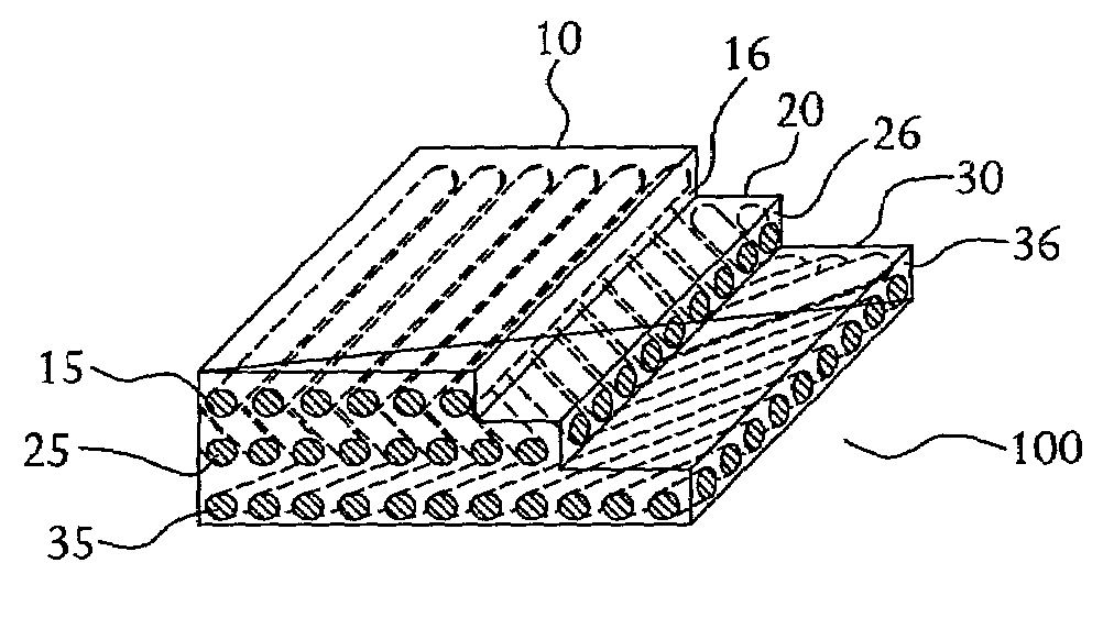
[0057]A tri-layered laminate was prepared using two plies of 600 g / m2 consolidated polypropylene glass Twintex® fabric sheet as the outer layers and a 400 g / m2 woven polypropylene fabric as the core layer. The core layer was bonded to the outer layers in a controlled way using a pair of polyethylene adhesive webs, such that a moderate amount of adhesion was achieved upon heating and pressing the combination of layers together. The resulting laminate exhibited higher shearout resistance, high impact and flexural strength and was capable of being recycled due to the presence of principally one thermoplastic matrix, and one fiber type, glass. This design was highly suitable for truck roof panels, highway signs and other fastened plate uses.

example b

[0058]Another tri-layered laminate was prepared by laminating together two 400 g / m2 consolidated polypropylene-glass Twintex® sheets as the outer skins. These skins were combined with a core layer of 300 g / m2 woven aramid fiber (Kevlar®) and consolidated at 200° C. (400° F.), below the melting point of Kevlar®. Alternatively, the Twintex® sheets can be consolidated independently and then glued or joined with polyethylene adhesive webs, or the layers laminated with heated press rolls. The Kevlar® fiber could contain a compatible coating, such as polypropylene, to improve adhesion. The resulting composite was combined with heat and pressure, and resulted in a highly explosion-resistant panel suitable for air cargo containers and cockpit doors.


PUM

PropertyMeasurementUnit
elongation at breakaaaaaaaaaa

Abstract

This invention provides multi-layered composites, laminates and composite joints in which at least one resin-impregnated, fiber-containing layer is joined or laminated to a core layer having a lower flexural modulus or higher elongation at break, higher toughness, or a combination of all or some of these properties. The multi-layer composite produced by laminating or joining these materials together has improved shearout, impact and cutting resistance, since stresses caused by outside forces can be more widely distributed throughout the composite.

Description

FIELD OF THE INVENTION[0001]This invention relates to composite joints generally, and more specifically, to composite joints including at least one multi-layered composite having at least two layers of different toughness for helping to retard bearing stress and shearout stress.BACKGROUND OF THE INVENTION[0002]Fiber-reinforced composites are relatively brittle compared to conventional ductile metal alloys, such as stainless steel and aluminum. Yielding of ductile metals usually reduces the stress concentration around bolt holes so that there is only a loss of area, with no stress concentration at ultimate load on the remaining section at the joints. With composites, however, there is no relief at all from the elastic stress concentration, and catastrophic failure usually results without much warning. Even for small defects in composite structures, the stress-concentration relief is far from complete, although the local disbanding between the fibers and resin matrix and local intrapl...

Claims


Application Information

Patent Timeline
Patent Type & Authority Patents(United States)
IPC IPC(8): B23B7/08B29C65/00B29C70/08B32B5/28B32B27/04B32B27/12H05K1/03
CPCB29C66/721B29C70/083B32B5/28B32B27/04H05K1/0366B32B27/12Y10S428/911H05K1/036H05K2201/0278B29C66/7212B29C66/72143B29C66/7392B29C66/7394B29C66/71B29C66/72141B29C65/02B29C66/72328B29C66/72327B29C66/723B29C66/72321Y10T442/69Y10T442/607Y10T442/659Y10T442/2361Y10T442/2623Y10T442/291Y10T442/2754Y10T442/2861Y10T442/2902Y10T428/249923Y10T442/2615Y10T442/2992Y10T442/604Y10T442/2893Y10T442/697Y10T442/2926Y10T442/2738B29K2307/04B29K2077/00B29K2309/08B29K2277/10B29K2023/04B29K2027/06B29K2071/00B29K2079/085B29K2081/06B29K2067/00B29K2081/04B29K2063/00B29K2055/02B29K2301/00B29K2077/10B29K2071/12B29K2067/06B29K2025/08B29K2025/06B29K2023/12B29K2023/06
Inventor PORTER, JOHN FREDERICK
Owner SAINT GOBAIN TECHN FABRICS CANADA
Why Eureka
Try Eureka