Power slope targeting for DC generators

Inactive Publication Date: 2006-08-08
SUSTAINABLE ENERGY SYST
View PDF20 Cites 211 Cited by
  • Summary
  • Abstract
  • Description
  • Claims
  • Application Information

AI Technical Summary

Benefits of technology

[0018]In essence, according to various principles of this invention, a simple feedback control loop coupled with a power slope targeting power control system can ensure efficient operation of a power generator. The power slope targeting power control system operates the generator at a maximum allowable power point, determined based on the characteristics of that particular generator, at all times. The feedback control loop, by measuring a power output of

Problems solved by technology

The maximum allowable power point represents a power output lev

Method used


Image

  • Power slope targeting for DC generators
  • Power slope targeting for DC generators
  • Power slope targeting for DC generators

Examples


Embodiment Construction

[0025]The principles of the present invention will be described more fully hereinafter with reference to preferred embodiments thereof. It should be noted, however, that the following embodiments may be modified in various forms, and that the scope of the present invention is not limited to these specific embodiments. The embodiments of the present invention are provided by way of example, and not by way of limitation.

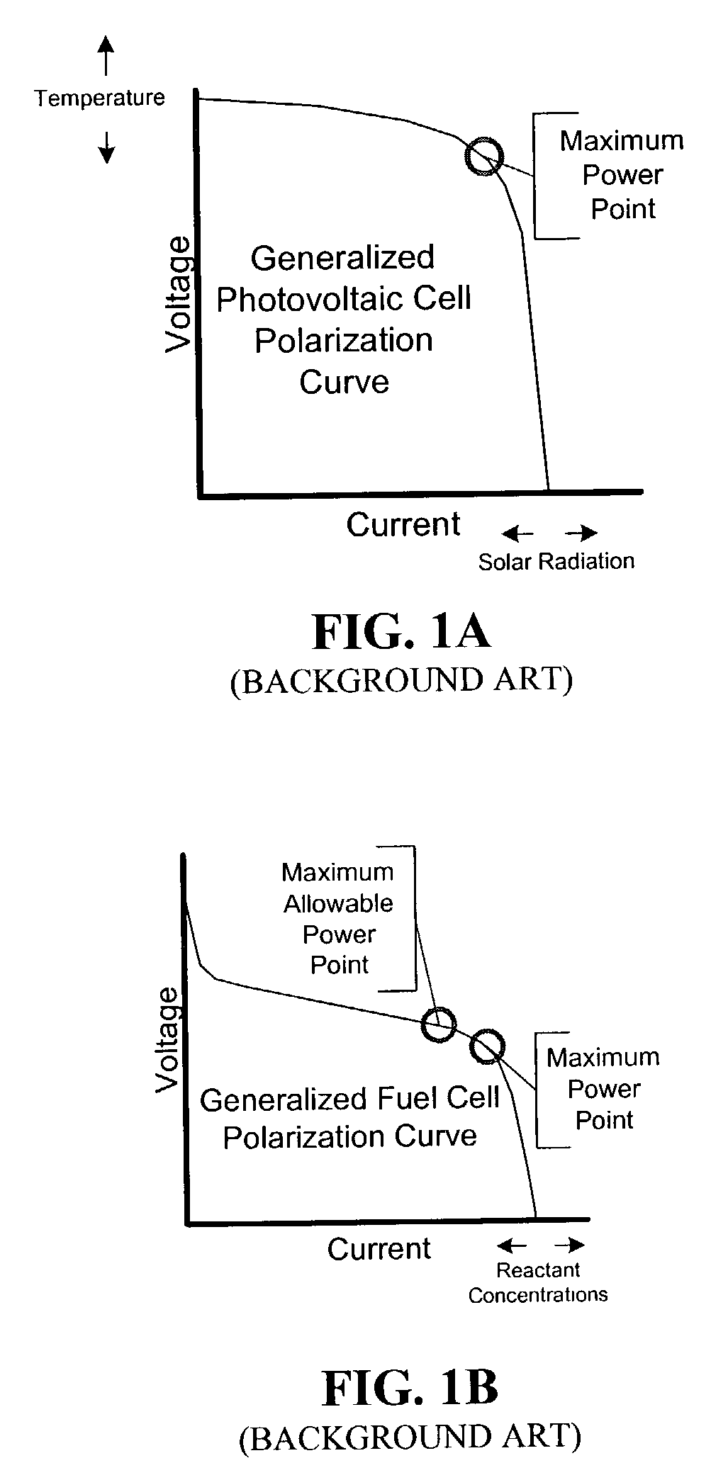
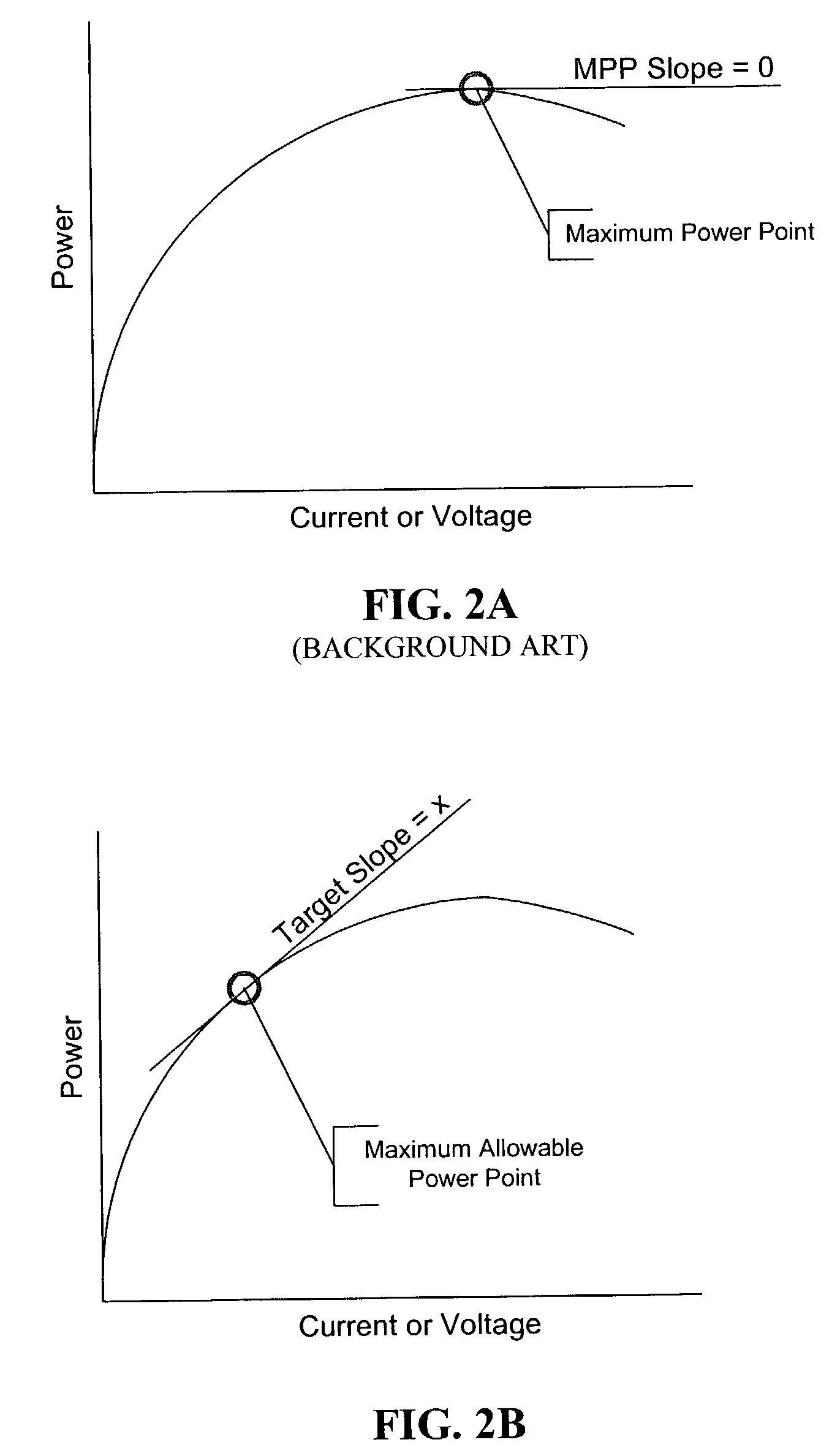
[0026]Conventional methods of maximum power point tracking, as applied to PV cells and DC wind turbines, generally search for the global power maximum. This is the point where the slope of the power curve is approximately zero or the point on the polarization curve where the percent change in voltage is equal and opposite to the percent change in current. Unfortunately, however, for various reasons, this method has not been readily applicable to fuel cell systems.

[0027]Although the industry would benefit from the application of a maximum power point tracking method to ...


PUM


Abstract

A simple feedback control loop, in conjunction with an improved maximum power point tracking intermediate controller, can be used ensure efficient operation of a power generator. The improved maximum power point tracking controller operates the generator at its maximum allowable power point. A power output of the generator is measured and compared to a power output setpoint. Operating characteristics of the generator are then adjusted to cause the maximum allowable power point and measured power output to approximate the power output setpoint. Although applicable to all types of generators, this is particularly beneficial in fuel cell generator systems and other systems where damage to generator components can occur if operated above a maximum allowable power output level. In other systems, the maximum allowable power output may approach or equal a maximum power point (or maximum possible power point).

Description

BACKGROUND OF THE INVENTION[0001]1. Field of the Invention[0002]The present invention relates to a method of efficiently operating a direct current (DC) generator. More particularly, this invention relates to a method of using power curve characteristics of a DC generator to operate the generator efficiently.[0003]2. Description of the Related Art[0004]A DC generator (such as a photovoltaic (PV) cell, a fuel cell, a wind turbine, or a microturbine, for example) has a polarization curve that represents a relationship between voltage and current generated by the generator. The polarization curve varies depending on the operating conditions of the DC generator.[0005]FIG. 1A is a generalized polarization curve for a PV cell. As shown in FIG. 1A, the polarization curve of a PV cell varies depending primarily on cell temperature and on an amount of solar radiation incident on the cell. In a DC generator, PV cells can be interconnected together to form a stack or array having a higher powe...

Claims


Application Information

Patent Timeline
IPC IPC(8): H01M8/04G05F1/67
CPCG05F1/67
Inventor HARRIS, BRENT EARLE
Owner SUSTAINABLE ENERGY SYST
Why Eureka
Try Eureka