Battery module

a battery cell and module technology, applied in the field of batteries, can solve the problems of degrading the performance of the secondary battery, and the electrolytic solution does not in fact effectively prevent the volume increase, and achieves the effect of suppressing the volume increase of the battery cell and reducing the weigh

Active Publication Date: 2006-08-08
NEC CORP
View PDF13 Cites 18 Cited by
  • Summary
  • Abstract
  • Description
  • Claims
  • Application Information

AI Technical Summary

Benefits of technology

[0006]It is therefore an object of the present invention to provide a battery module including a plurality of flat secondary battery cells, which is capable of effectively suppressing the volume increase of the battery cell and has a smaller weight.
[0008]In accordance with the battery module of the present invention, provision of the intervention member between the pressure plate and the corresponding portion of the housing at the central area of the pressure plate allows reduction of the pressure applied onto the peripheral area of the battery cell, wherein the battery cell is applied with a substantially uniform pressure by the pressure plates even if the housing has a warp.

Problems solved by technology

It is generally known that a secondary battery has a drawback in that the iterative charge and discharge operation causes generation of internal gas, which enters between electrodes of the battery cell to degrade the performance of the secondary battery.
In particular, a secondary battery cell having a laminate overcoat suffers from a volume increase within the overcoat due to the internal gas to enlarge the gap between the electrodes of a battery body, thereby largely degrading the performance of the secondary battery.
However, such an electrolytic solution does not in fact effectively prevent the volume increase due to the gas generation during the long lifetime of the secondary battery.
In addition, the structure configured to suppress the increase of the electrode gap increases the weight per unit cell, thereby reducing the current storage capacity per unit weight of the secondary battery or a module including a plurality of such secondary batteries.

Method used


Image

  • Battery module
  • Battery module
  • Battery module

Examples


first embodiment

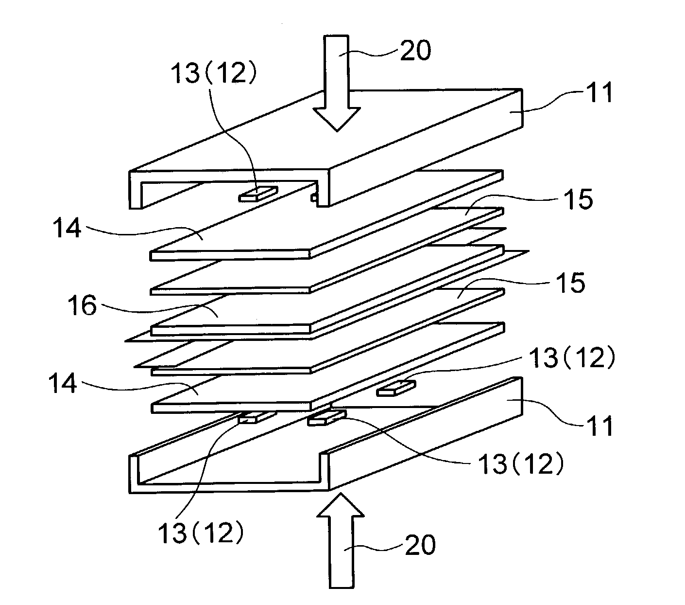
[0024]Now, the present invention will be described in more detail based on the preferred embodiments thereof with reference to the drawings. Referring to FIG. 1, a battery module according to the present invention includes a battery cell 16 including a laminate overcoat and a battery body having an iterative structure such as described in the conventional battery module, a pair of rubber plates 15 sandwiching therebetween the battery cell 16, a pair of pressure plates 14 sandwiching therebetween the rubber plates 16 and battery cell 15, a pair of housing members 11 sandwiching therebetween the pressure plates 14, rubber plates 15 and battery cell 16, and an intervention member 12 interposed between each of the pressure plates 14 and a corresponding one of the housing members 11 at the central area of the pressure plates 14. The intervention member 12 in this embodiment includes four poles, or rectangular prisms 13 disposed at four apexes of a rectangle. The pair of housing members 1...

second embodiment

[0041]As understood from tables 1 and 2, the samples of the battery module also achieved improvement in the capacity remaining ratio by around 10% at a maximum after 500 cycles compared to the conventional battery module. In particular, an applied pressure as low as 0.1 kgf / cm2 can achieve an improvement of around 5% in the capacity remaining ratio.

third embodiment

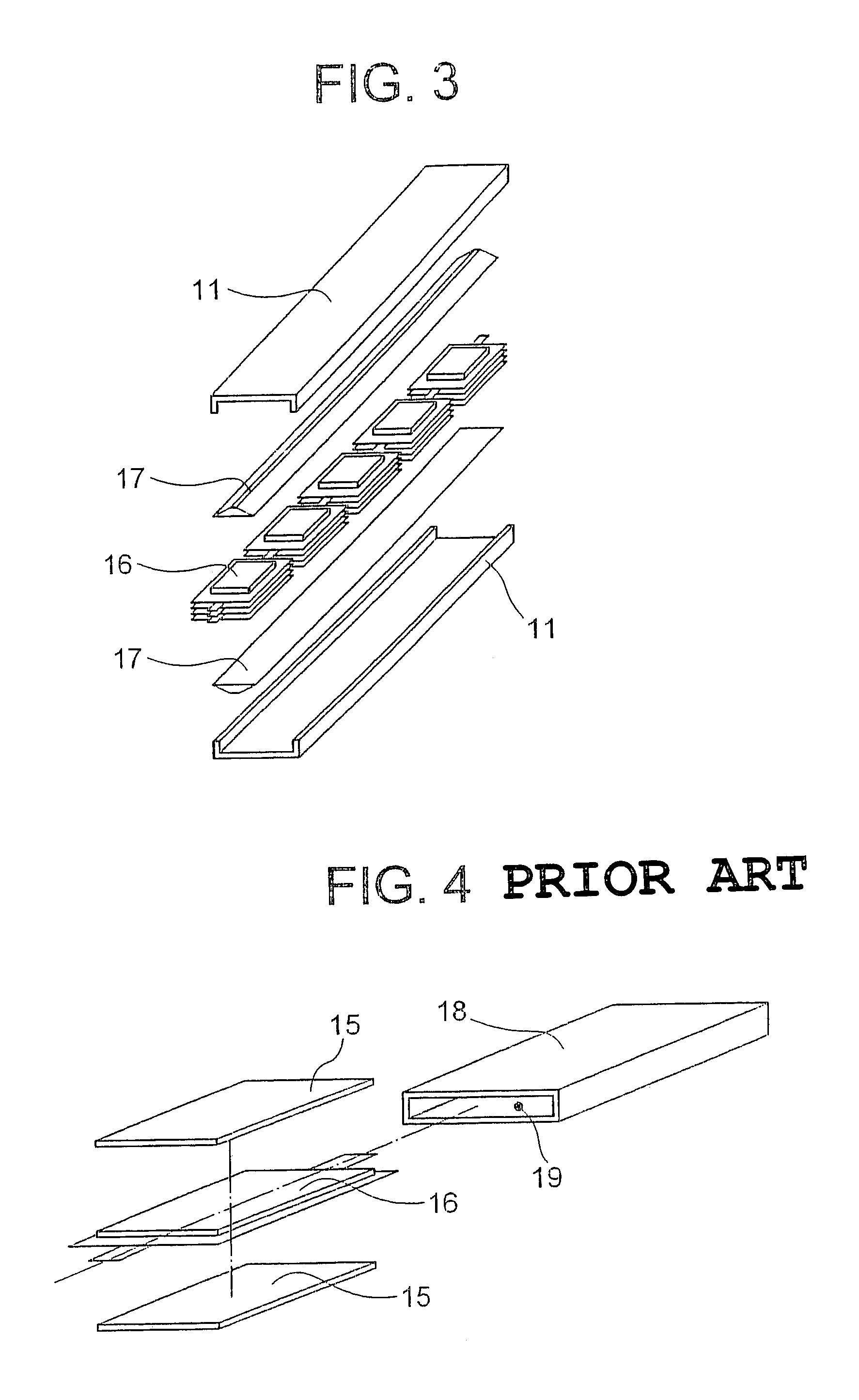
[0042]Referring to FIG. 3, a battery module according to the present invention, including twenty battery cells 16 which are electrically connected in series and stacked up to four levels and arranged as a train including five battery stacks.

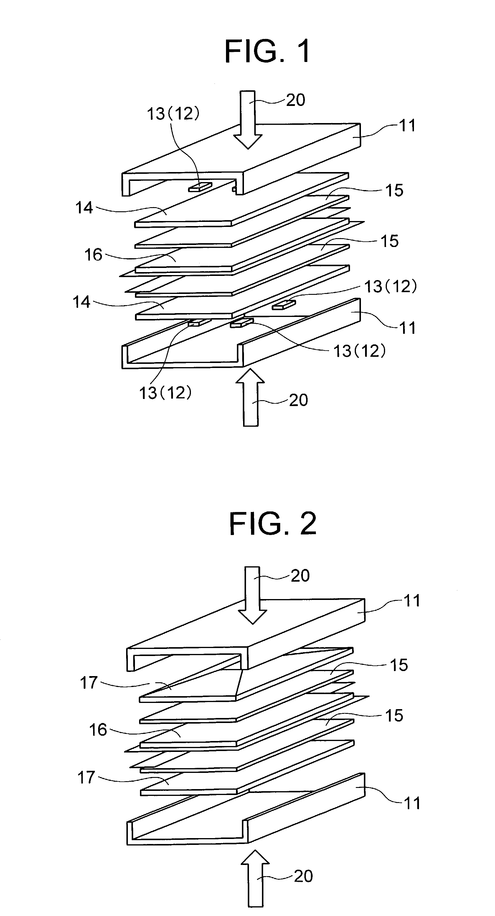
[0043]The battery cells 16 as a whole are sandwiched between a pair of pressure plates 17 having a part of pyramid shape, which are sandwiched between a pair of housing members 11. The external force 20 applied to the battery module causes battery module to wrap so that the pressure plates 17 and a corresponding portion of the housing 11 are contact with each other at a peripheral area as seen in FIG. 6. The battery module has excellent characteristics after the charge and discharge operation, and has a smaller weight due to the resin material used for the battery module.


PUM

PropertyMeasurementUnit
thickaaaaaaaaaa
thickaaaaaaaaaa
thickaaaaaaaaaa

Abstract

A battery module includes a battery cell having a laminate overcoat, a pair of rubber sheets, a pair of pressure plates, and a pair of housing members from the internal to the external of the battery module. An intervention member including four poles is interposed between the pressure plate and the housing member at the central area of the battery cell to alleviate the stress concentration on the peripheral area of the battery cell. The intervention member may be formed separately from or integrated with the pressure plate.

Description

BACKGROUND OF THE INVENTION[0001](a) Field of the Invention[0002]The present invention relates to a battery module and, more particularly, to the structure of a module battery including a flat secondary battery.[0003](b) Description of the Related Art[0004]It is generally known that a secondary battery has a drawback in that the iterative charge and discharge operation causes generation of internal gas, which enters between electrodes of the battery cell to degrade the performance of the secondary battery. In particular, a secondary battery cell having a laminate overcoat suffers from a volume increase within the overcoat due to the internal gas to enlarge the gap between the electrodes of a battery body, thereby largely degrading the performance of the secondary battery.[0005]For solving the above problem in a battery module including a battery cell having a laminate overcoat, an electrolytic solution having a function for suppressing the gas generation and / or a cell structure conf...

Claims


Application Information

Patent Timeline
Patent Type & Authority Patents(United States)
IPC IPC(8): H01M2/04H01M2/02H01M2/00H01M2/10H01M10/02H01M10/04
CPCH01M2/0469H01M10/0481H01M10/0468H01M10/0413Y02E60/10Y02P70/50H01M50/20
Inventor KANETA, HIROSHI
Owner NEC CORP
Why Eureka
Try Eureka