Charge pump with constant output current

a charge pump and output current technology, applied in the field of integrated circuits, can solve the problems of reducing the delivering a constant output current, and reducing the charge rate of the charge pump, so as to enhance the overall efficiency of the charge pump circuit, increase the current, and enhance the effect of efficiency

Inactive Publication Date: 2006-08-08
TEXAS INSTR INC
View PDF10 Cites 4 Cited by
  • Summary
  • Abstract
  • Description
  • Claims
  • Application Information

AI Technical Summary

Benefits of technology

[0007]In accordance with the present invention, an improved charge pump circuit is provided that is capable of producing a constant output current. The presently disclosed charge pump circuit achieves such benefits by employing a controllable current source that produces a controlled current that increases as the output level of the charge pump increases.
[0008]In one embodiment, the charge pump circuit includes a controllable current source, at least one switching element coupled between the controllable current source and an output node, and a load capacitor coupled between the output node and ground potential. The switching element is configured to switch in response to an input signal to allow current pulses to flow from the controllable current source through the output node. Further, the load capacitor is operative as an integrator to convert the output current pulses into a voltage level. The controllable current source is configured to provide increased current levels as the output voltage level of the charge pump increases, thereby enhancing the overall efficiency of the charge pump circuit.
[0009]By increasing the current charging the output node as the output voltage level increases, the charge pump circuit provides enhanced efficiency over an extended range of operating conditions.

Problems solved by technology

One drawback of the conventional charge pump circuit is that as the output level increases the efficiency of the charge pump frequently decreases, which can manifest itself in a reduction in the charge rate of the charge pump over time.
This is, at least in part, because the conventional charge pump is often incapable of delivering a constant output current.
Such inefficiency can also make the conventional charge pump susceptible to, e.g., unwanted output leakage currents and limited output slew rates.

Method used


Image

  • Charge pump with constant output current
  • Charge pump with constant output current
  • Charge pump with constant output current

Examples


Embodiment Construction

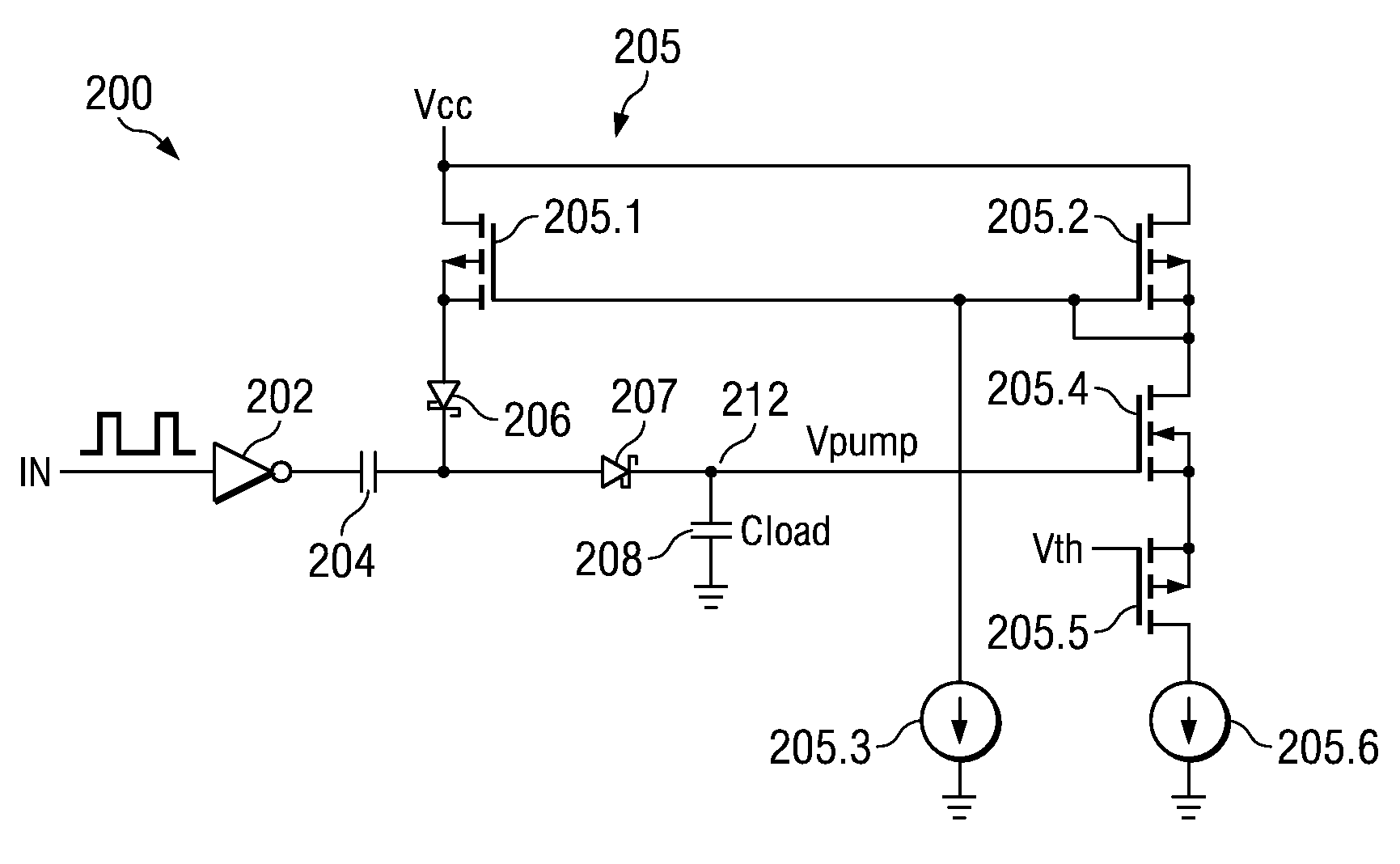
[0017]An improved charge pump circuit is disclosed that is capable of providing a constant output current. The presently disclosed charge pump circuit increases the current flowing to the charge pump output as needed to maintain the desired constant output current level, thereby providing enhanced efficiency over an extended range of operating conditions.

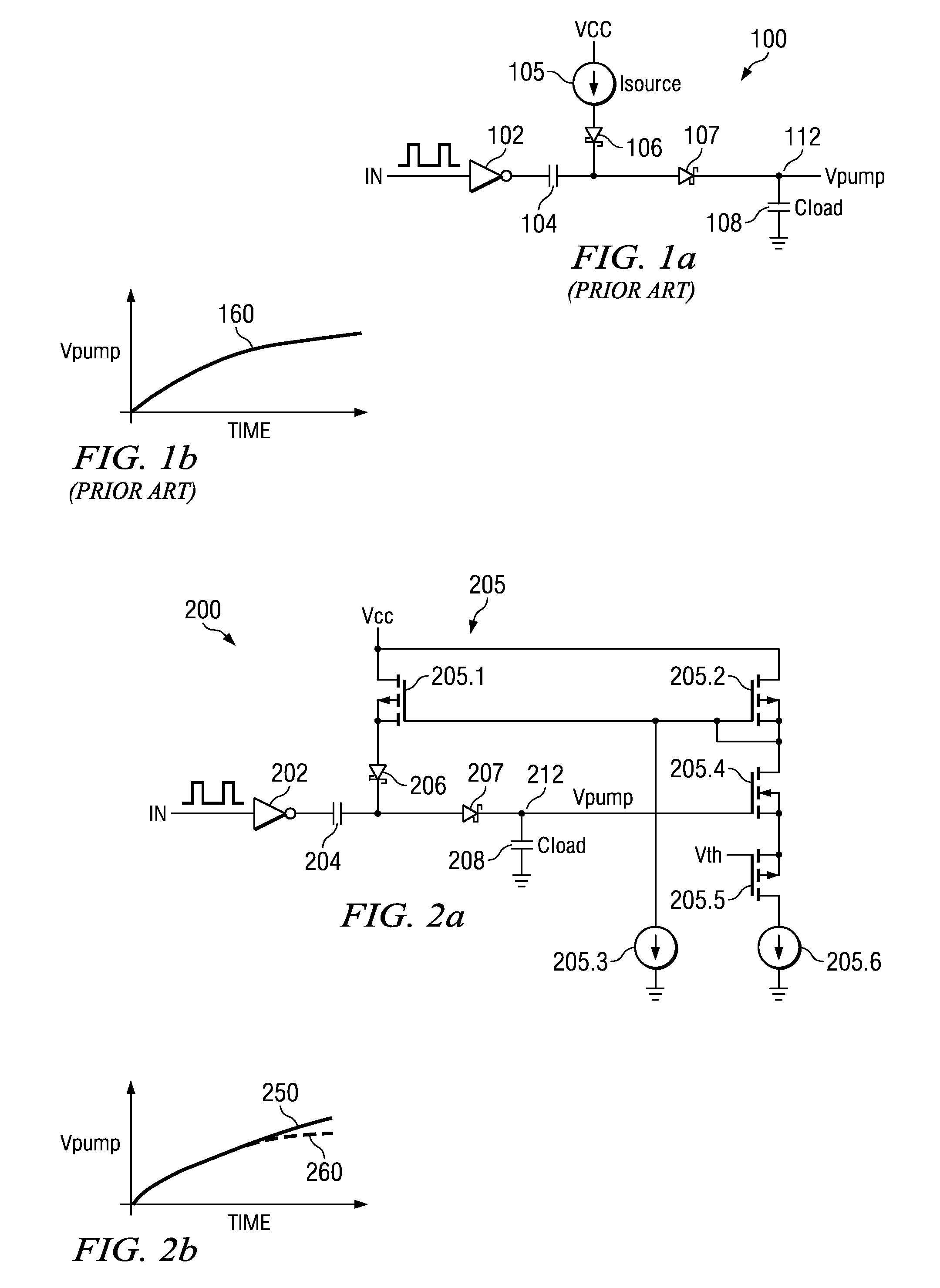
[0018]FIG. 1a depicts a conventional single stage charge pump circuit 100, which includes an input buffer configured as an inverter 102, a Direct Current (DC) blocking capacitor 104, a constant current source 105 providing a constant current Isource, a plurality of diodes 106–107, and a load capacitor (Cload) 108. In the illustrated embodiment, the inverter 102 receives an input (IN) signal comprising a series of binary logic pulses. In response to the applied logic level pulses, current pulses flow from the current source 105 through the diodes 106–107 to charge an output node 112 to a predetermined voltage level Vpump. Because the...


PUM


Abstract

An improved charge pump circuit that is capable of producing a constant output current. The charge pump circuit includes a controllable current source, at least one switching element coupled between the controllable current source and an output node, and a load capacitor coupled between the output node and ground potential. The switching element switches in response to an input signal to allow current pulses to flow from the controllable current source through the output node. The load capacitor operates as an integrator to convert the output current pulses into a voltage level. The controllable current source provides increased current levels as the output voltage level of the charge pump increases, thereby enhancing the overall efficiency of the charge pump circuit.

Description

CROSS REFERENCE TO RELATED APPLICATIONS[0001]N / ASTATEMENT REGARDING FEDERALLY SPONSORED RESEARCH OR DEVELOPMENT[0002]N / ABACKGROUND OF THE INVENTION[0003]The present application relates generally to integrated circuits, and more specifically to a charge pump circuit providing a constant output current.[0004]Charge pump circuits are known that may be employed in integrated circuits to charge one or more circuit nodes to predetermined voltage levels. For example, a conventional charge pump circuit may include at least one current source, at least one switching element coupled between the current source and an output node, and a load capacitor coupled between the output node and ground potential. In a typical mode of operation, the switching element switches in response to an input signal to allow current pulses to flow from the current source through the output node. Further, the load capacitor operates as an integrator to convert the current pulses into an output voltage level.[0005]O...

Claims


Application Information

Patent Timeline
Patent Type & Authority Patents(United States)
IPC IPC(8): G05F3/02H02M3/07
CPCH02M3/07H02M2001/0045H02M1/0045
Inventor NEIDORFF, ROBERT ALAN
Owner TEXAS INSTR INC
Why Eureka
Try Eureka