Housing structure for RFID tag, installation structure for RFID tag, and communication using such RFID tag

a technology of rfid tag and installation structure, which is applied in the direction of loop antennas with ferromagnetic cores, protective material radiating elements, instruments, etc., can solve the problems of endurance, plastic containers, and fear of damage to the rfid tag inside the plastic container

Inactive Publication Date: 2006-08-08
HANEX CO LTD
View PDF11 Cites 187 Cited by
  • Summary
  • Abstract
  • Description
  • Claims
  • Application Information

AI Technical Summary

Benefits of technology

[0014]The present invention is to solve the foregoing problems, and a first object thereof resides in providing a novel installation structure for an RFID tag, which effectively protects the RFID tag from external stress or impact during the storage, transportation and usage, and allows communication with the external.

Problems solved by technology

However, the container formed with a non-conductive material such as plastic raised a problem regarding endurance since the container is rather low resistant against outer force.
For example, in a case where the RFID tags contained respectively inside plastic containers are attached to numerous steel plates and individually managed, the steel plates tend to drop, fall or crumble during transportation or storage causing damage to the plastic containers and leading to a fear of damage of the RFID tag inside the plastic container.
Further, although a surface of the installed RFID tag requires to be covered by a protective member for protection from outside stress or shock, a conductive material being a barrier of communication could not be used as a material of the protective member for enabling the RFID tag to perform communication with a read / write terminal or the like outside of the protective member; therefore, a non conductive material such as plastic was generally used as the material of the container.
Nevertheless, since a strength of a non-conductive material such as plastic is relatively low, a protection of the RFID tag was often insufficient.
For example, in a case where an RFID tag is placed to a lid or the like of a metallic manhole, a problem regarding endurance of the RFID tag is raised since the RFID tag is continuously subject to a weight of the traffic of passing vehicles and the like.

Method used


Image

  • Housing structure for RFID tag, installation structure for RFID tag, and communication using such RFID tag
  • Housing structure for RFID tag, installation structure for RFID tag, and communication using such RFID tag
  • Housing structure for RFID tag, installation structure for RFID tag, and communication using such RFID tag

Examples


Embodiment Construction

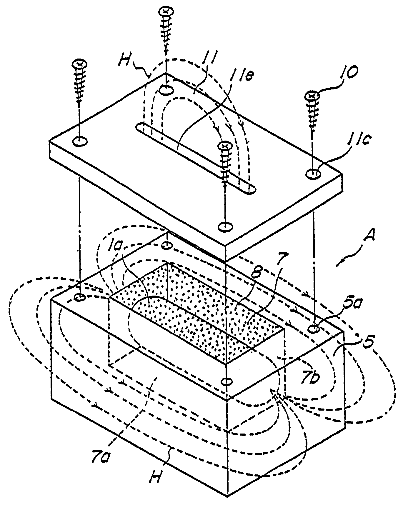
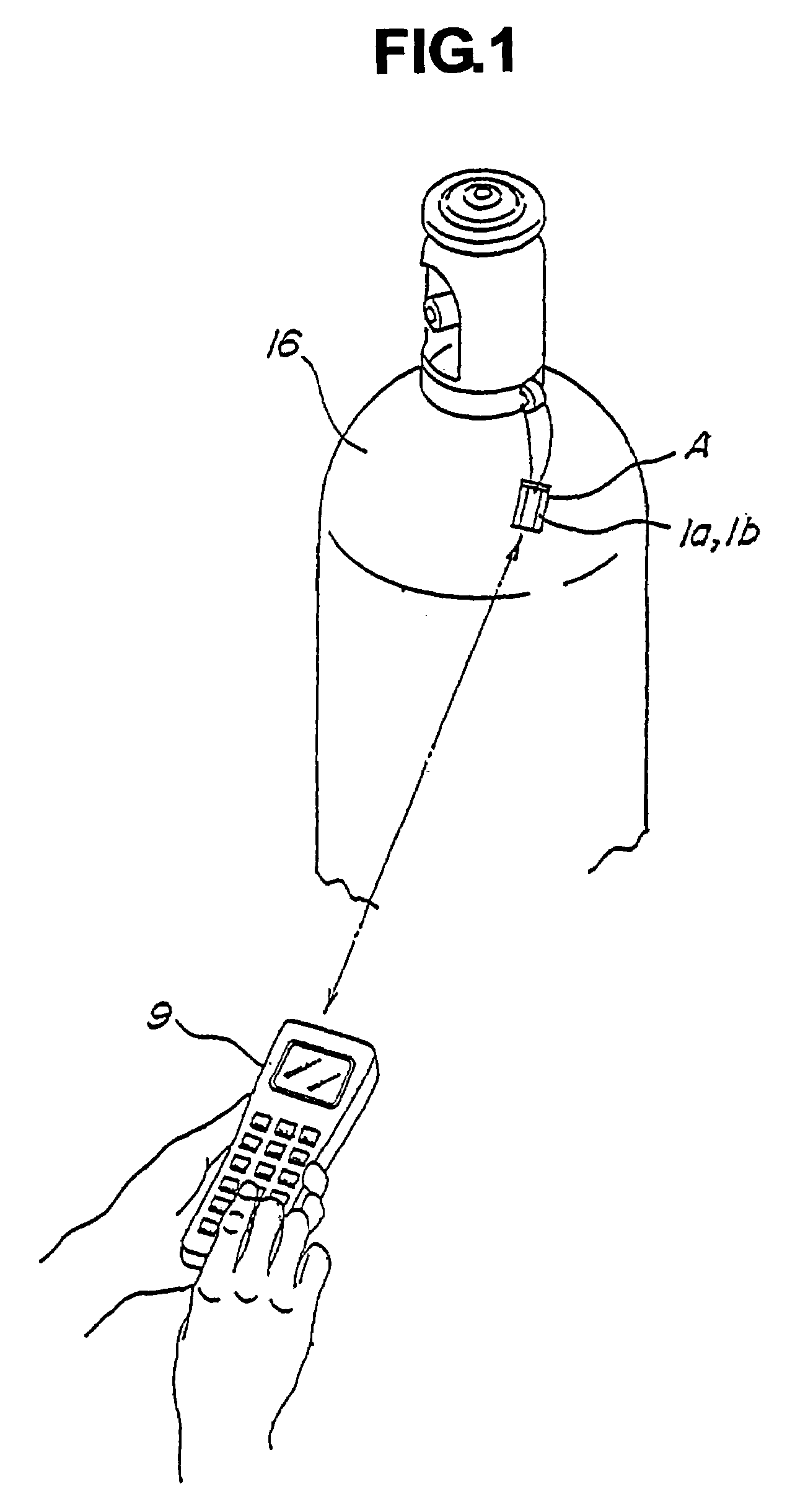
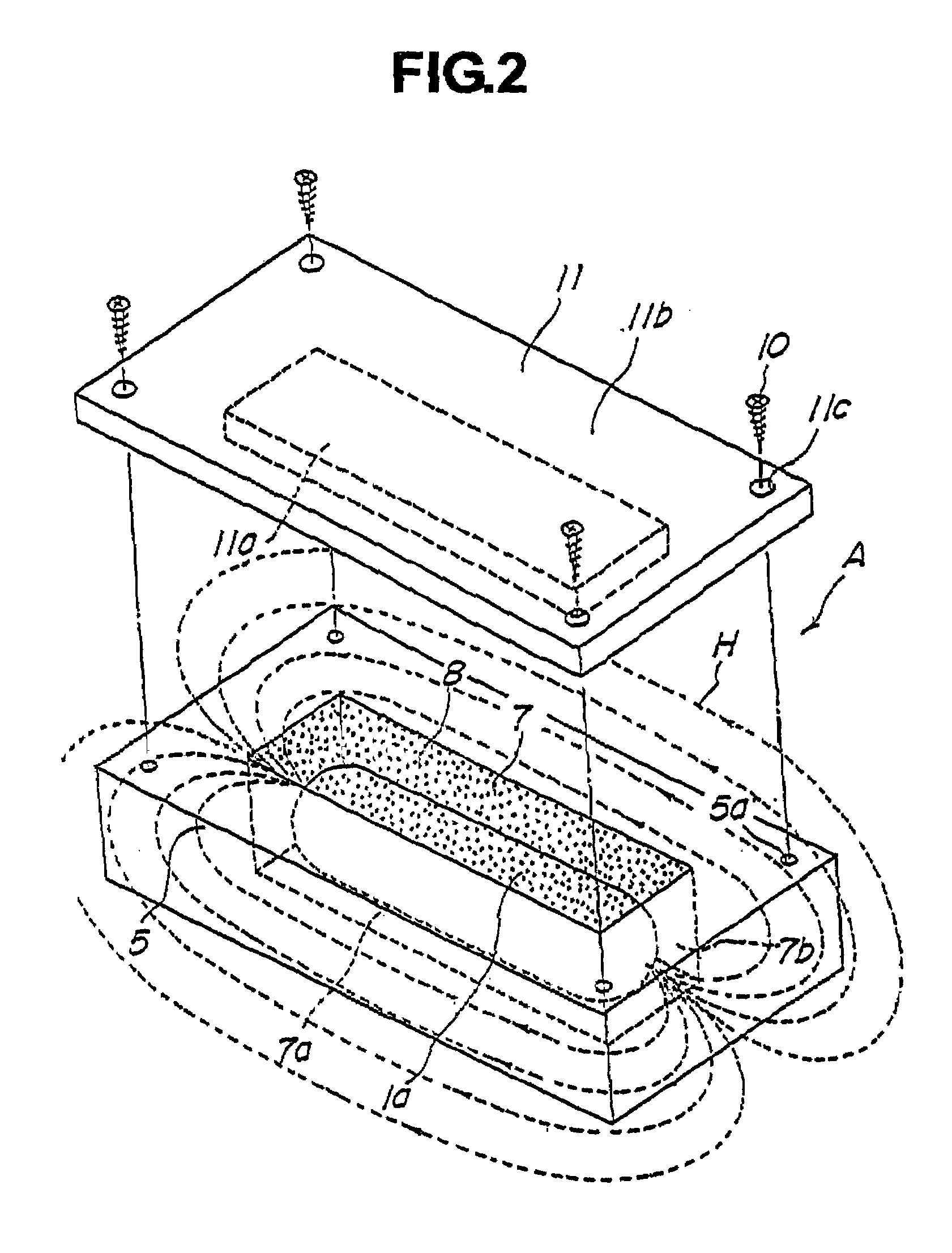
[0102]Embodiments of the housing structure, installation structure and communication method of the RFID tag of the present invention will specifically be explained referring to the attached drawings. FIGS. 1 to 11B are the drawings for explaining the housing structures, installation structures and communication methods of an RFID tag having a cylindrical antenna coil and housed in a container made of a conductive material; and FIGS. 12 to 16B are the drawings for explaining those for an RFID tag having a concentric disk shaped antenna coil housed in a similar manner.

[0103]First, referring to FIGS. 1 to 11B, housing structures, installation structures and communication methods of an RFID tag having a cylindrical antenna coil and being housed in a container made of a conductive material will be explained.

[0104]It should now be noted that the RFID tags 1a and 1b, preferably applicable to the embodiments described below, relate both to those of electromagnetic coupling type and electrom...


PUM


Abstract

A first object of the present invention resides in providing a novel installation structure for an RFID tag, which effectively protects the RFID tag from external stress or impact during the storage, transportation and usage, and allows communication with the external.
A second object of the present invention resides in that providing a novel installation structure for an RFID tag, which enables communication with the external even if the RFID tag is installed on a conductive member such as a metal member, and the surface thereof is covered with a protective member typically made of a metal which has an excellent strength and durability.
A third object of the present invention is to provide a communication method using an RFID tag as being surrounded by a conductive member typically made of a metal.
Even if an RFID tag 1a is housed in a container A typically made of a conductive material such as a metal having a large mechanical strength, the RFID tag 1a can communicate with an external read/write terminal 9 as mediated by leakage magnetic flux if only a flux leakage path 12 composed for example of a gap is formed in such container A.

Description

CROSS-REFERENCE TO RELATED APPLICATION[0001]The entire disclosure of Japanese patent application No. 2000-218443 filed on Jul. 19, 2000 and No. 2000-233888 filed on Aug. 2, 2000, including the specification, claims, accompanying drawings and abstract of the disclosure is incorporated herein by reference in its entirety, in order to claim priority right according to 35 U.S.C. §119.FIELD OF THE INVENTION[0002]The present invention relates to a housing structure, an installation structure and an installation method in which an RFID having an antenna coil and a control sectionDESCRIPTION OF THE RELATED ART[0003]Conventional RFID (Radio Frequency IDentification) tags are roughly classified into those of the electromagnetic induction type and the electromagnetic coupling type; both of which are designed to communicate in a non-contact manner with a read / write terminal or so using electromagnetic wave.[0004]The RFID tag has an antenna coil and a control section, in which a signal sent from...

Claims


Application Information

Patent Timeline
Patent Type & Authority Patents(United States)
IPC IPC(8): G08B13/14G06K7/08G06K19/04G06K19/077H01Q1/22H01Q1/42H01Q7/00
CPCG06K7/10336G06K19/041G06K19/07728G06K19/07749G06K19/07758H01Q7/00G06K19/07777H01Q1/22H01Q1/2225H01Q1/42G06K19/07771G06K17/00
Inventor SENBA, FUJIOHYODO, NAKAMAROFUJII, JUNUCHIYAMA, TOMOKIKIDA, SHIGERU
Owner HANEX CO LTD
Why Eureka
Try Eureka