
Lens antenna

a technology of lens body and antenna, applied in the direction of antennas, instruments, electrical equipment, etc., can solve the problems of unsuitability of each known detection system, repeated exposure to undesired thermal expansion or shrinkage, and too high production cost of lens body, etc., to achieve excellent resistance to cracks

Inactive Publication Date: 2006-08-08
MURATA MFG CO LTD
View PDF28 Cites 4 Cited by
  • Summary
  • Abstract
  • Description
  • Claims
  • Application Information

AI Technical Summary

Benefits of technology

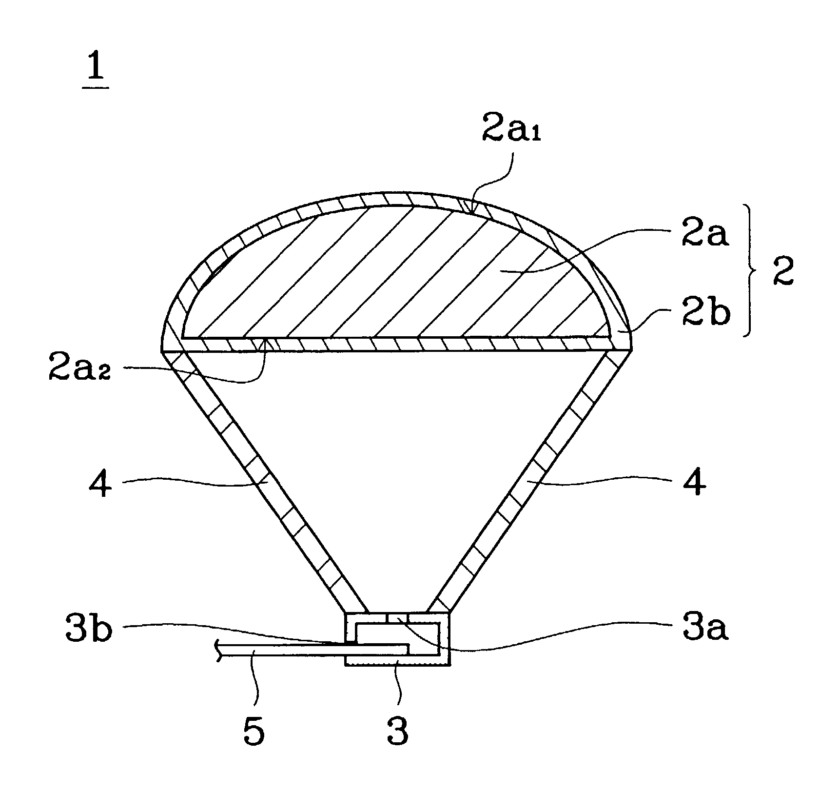
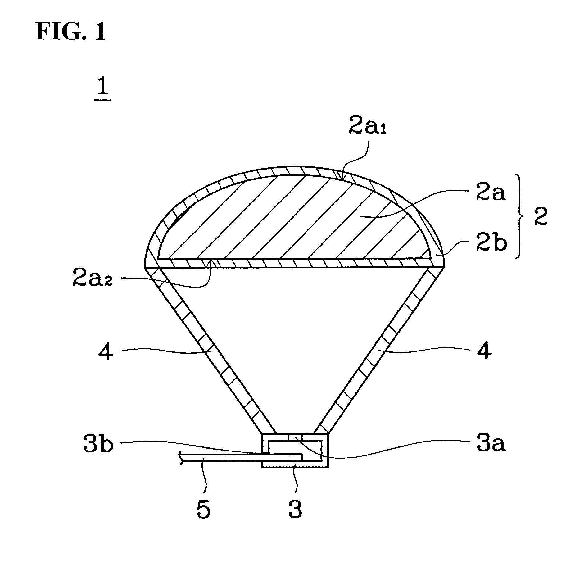
[0009]Accordingly, it is an object of the present invention to provide an improved lens antenna having an excellent resistance against cracks due to thermal expansion or thermal shrinkage.
[0011]With the use of the above arrangement, it is possible to prevent the occurrence of cracks in the lens body. This is because the thermoplastic elastomers have a desired rubber elasticity which is useful for relaxing stresses caused by thermal expansion or thermal shrinkage of the lens body.
[0013]With the use of the above arrangement, it is possible to prevent the occurrence of cracks in the lens body as well as in the matching layer.
[0015]With the use of the above arrangement, it is possible to increase the dielectric constant of the lens body, thereby allowing the lens body to be made thinner.
[0017]With the use of the above arrangement, it becomes possible to adjust the dielectric constants of both the lens body and the matching layer, thereby ensuring a conformity between the two members. Preferably, if the dielectric constant of the lens body is ∈ra and the dielectric constant of the matching layer is ∈rb, and if the two dielectric constants are in a condition satisfying an equation of ∈rb=(∈ra)½, it is possible to obtain a maximum conformity between the lens body and the matching layer, as well as to ensure a minimum reflection from the lens body.

Problems solved by technology

However, each of the known detection systems has been found unsuitable for use in rainy weather, or too expensive in their production cost.
However, with the above-described conventional lens antenna, a high temperature condition will cause the surface of the lens body or the matching layer to become oxidized and thus deteriorated, so that the lens body will be repeatedly exposed to an undesired thermal expansion or shrinkage.
As a result, a stress remaining within the lens body will be applied to the surface thereof or to the matching layer, resulting in cracks occurring in the lens body or the matching layer.
Whenever such cracks occur, not only will the appearance of the lens antenna become worse, but also moisture will invade into the lens antenna, bringing about an undesired change in the lens characteristic.
As a result, it will be difficult for the lens antenna to provide a desired gain.

Method used


Image

  • Lens antenna
  • Lens antenna

Examples


example

[0035]The following is a description explaining how to manufacture the preferred embodiments of the lens body and the matching layer of the lens antenna of the present invention.

[0036]First, the weight of several sorts of resin powders and several sorts of dielectric ceramic powders are taken using a balance so as to prepare materials A to N shown in Table 1. Then, an extruder of a biaxial type with its cylinder temperature at 200° C. is used to knead and thus mix together the various materials in a melted state so as to obtain a kneaded admixture. The obtained admixture is thereafter forced through a head hole so as to be formed into a thread-like (strand) material which is then cooled in water and subsequently cut into pellets. Preferably, each pellet has a diameter of 2 mm and a length of 5 mm. It is also possible to crush the admixture produced by the extruder into pellets by means of a crusher.

[0037]When preparing a composite dielectric material containing several sorts of resi...


PUM

PropertyMeasurementUnit
particle sizeaaaaaaaaaa
specific surface areaaaaaaaaaaa
particle sizeaaaaaaaaaa

Abstract

A lens antenna including a lens body and / or a matching layer. In the lens antenna, lens body may be formed by a material containing thermoplastic elastomers. When a matching layer is formed on the surface of the lens body, at least one of the lens body and the matching layer is formed by a material containing thermoplastic elastomers. The use of thermoplastic elastomers in the lens body and / or the matching layer assist in reducing the formation of cracks therein.

Description

BACKGROUND OF THE INVENTION[0001]1. Field of the Invention[0002]The present invention relates to a lens antenna.[0003]2. Description of the Related Art[0004]In recent years, active research and development have been going on for producing various types of ITS (Intelligent Transport Systems) suitable for use in a new generation. As a result, more and more functions have been used to ensure safe travel in an automobile. In particular, an outside environment detection system, which serves as an eye for an automobile, is considered to be the most important among various types of ITS. For example, there has been developed a detection system using an infrared ray or CCD. However, each of the known detection systems has been found unsuitable for use in rainy weather, or too expensive in their production cost.[0005]In view of the above, it is desirable to use, as an outside environment detection system, a radar which employs a millimeter wave (76 GHz). An antenna suitable for receiving such...

Claims


Application Information

Patent Timeline
Patent Type & Authority Patents(United States)
IPC IPC(8): H01Q15/08G02B1/04G01S7/03G02B3/00H01Q19/08
CPCH01Q19/08H01Q15/08
Inventor SAKURADA, KIYOYASUNONGAKI, HIROSHI
Owner MURATA MFG CO LTD
Learn More