Computation circuit having dynamic range extension function
a computation circuit and dynamic range technology, applied in the field of computation circuits, can solve the problems of inability to obtain accurate computation results, inability to accurately represent the upper bit of computation, and inability to calculate accurately, etc., to achieve the effect of low cost, dynamic range and low cos
- Summary
- Abstract
- Description
- Claims
- Application Information
AI Technical Summary
Benefits of technology
Problems solved by technology
Method used
Image
Examples
first embodiment
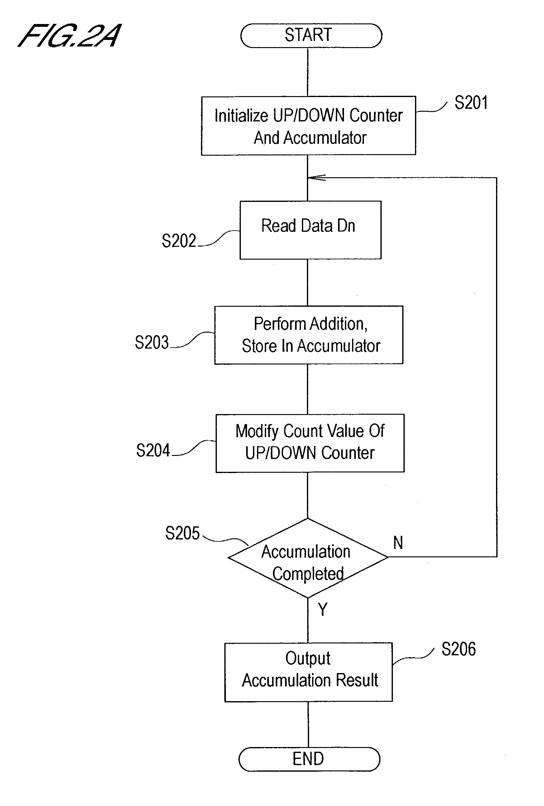
[0026]Below, a first aspect of the invention is explained, using FIG. 1 through FIG. 3B.
[0027]This aspect is explained adopting as an example a case in which the dynamic range is to be extended from 16 bits to 24 bits.
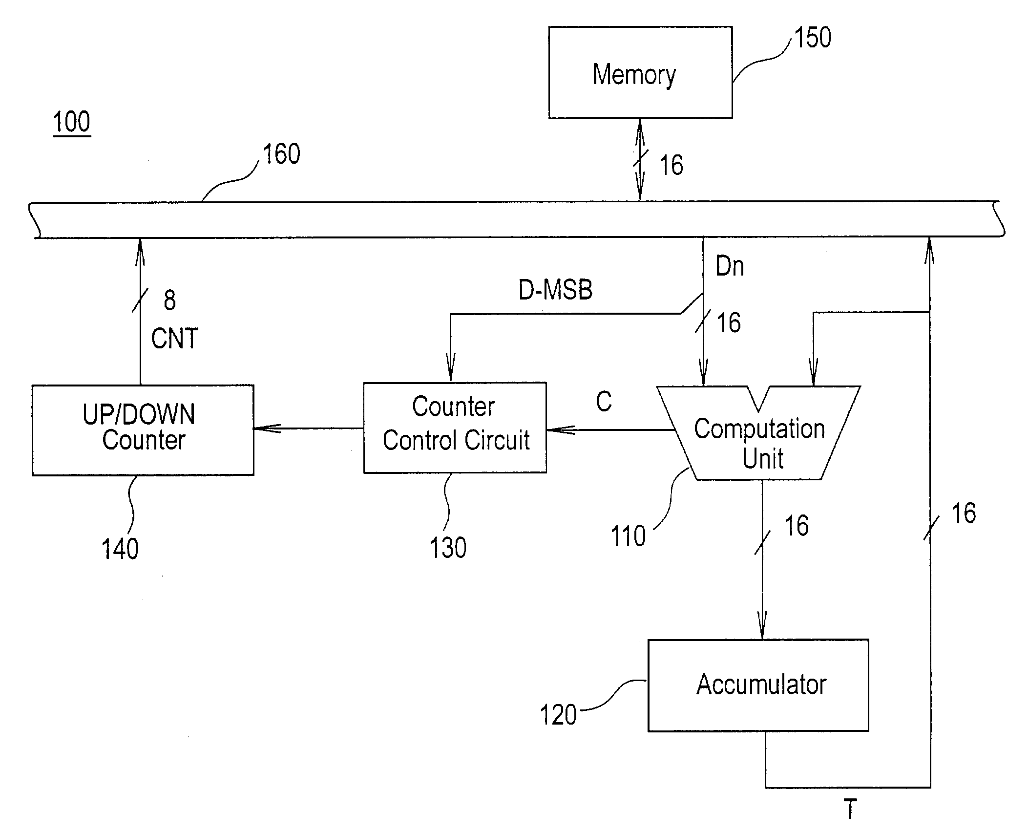
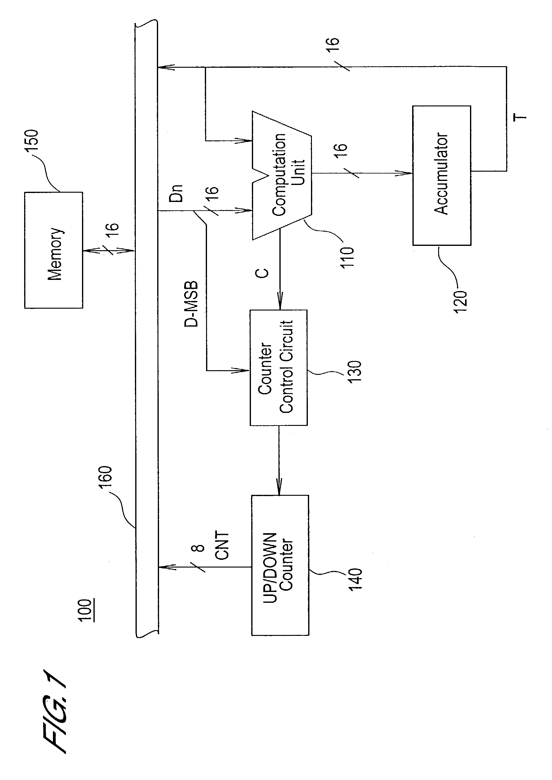
[0028]FIG. 1 is a block diagram showing the configuration of the computation circuit of this aspect.
[0029]As shown in FIG. 1, this computation circuit 100 comprises a computation unit 110, accumulator 120, counter control circuit 130, up / down counter 140, memory 150, and data bus 160.
[0030]The computation unit 110 computes the sum of data input from one input terminal and the data input from the other input terminal. One of the input terminals of the computation unit 110 is connected to the data bus 160. The other input terminal of the computation unit 110 is connected to the output terminal of the accumulator 120. In addition, the computation unit 110 outputs a carry signal C when carryover of the computation result occurs. As a computation unit 110, for example, a ge...
second embodiment
[0054]Next, FIGS. 4 through 6B are used to explain a second aspect of the invention.
[0055]This aspect is explained using as an example a case in which, like the first aspect, the dynamic range is extended from 16 bits to 24 bits.
[0056]FIG. 4 is a block diagram showing the configuration of the computation circuit of this aspect.
[0057]In FIG. 4, components to which are assigned the same symbols as in FIG. 1 are the same as in FIG. 1.
[0058]The computation unit 410 computes the sum of data input from two input terminals. In the computation unit 410, one of the input terminals is connected to the data bus 160, and the other input terminal is connected to the output terminal of the accumulator 120. The computation unit 410 outputs an overflow signal OF when an overflow occurs in the computation result. Also, the computation unit 410 outputs the R-MSB bit of the computation result (that is, bit B15 in FIG. 2B). As the computation unit 410, for example, an ordinary ALU (arithmetic logic uni...
third embodiment
[0091]Below a third aspect of the invention is explained, using FIG. 7 and FIG. 8. This aspect explains as an example a case in which the dynamic range is extended from 16 bits to 24 bits.
[0092]The computation circuit of this aspect is configured such that two kinds of accumulation are executed in parallel.
[0093]FIG. 7 is a block diagram showing the configuration of a computation circuit of this aspect.
[0094]In FIG. 7, components to which are assigned the same symbols as in FIG. 1 are the same as in FIG. 1.
[0095]The computation circuit 700 comprises two accumulators 710, 720. The accumulators 710, 720 are registers which temporarily store the computation results output from the computation unit 110. In this aspect, the bit widths of the accumulators 710 and 720 is 16 bitsi.
[0096]The selector 730 takes as input the stored values T1, T2 from the accumulators 710, 720, and selectively outputs these stored values to the computation unit 110 or to the data bus 160.
[0097]The counter contr...
PUM
 Abstract
Description
Claims
Application Information
 - R&D
- Intellectual Property
- Life Sciences
- Materials
- Tech Scout
- Unparalleled Data Quality
- Higher Quality Content
- 60% Fewer Hallucinations
Browse by: Latest US Patents, China's latest patents, Technical Efficacy Thesaurus, Application Domain, Technology Topic, Popular Technical Reports.
© 2025 PatSnap. All rights reserved.Legal|Privacy policy|Modern Slavery Act Transparency Statement|Sitemap|About US| Contact US: help@patsnap.com


