Optical angle sensor

a technology of optical/electrical converter and angle sensor, which is applied in the direction of measuring apparatus bearing/suspension, application, electrical/magnetic means, etc., can solve the problems of high mechanical support and the required precision mechanics, relative high cost and high cost of mechanical support, and achieves the effect of small distance between the rotating member and the static or stationary member and/or the optical/electrical converter

Inactive Publication Date: 2006-08-15
SICK STEGMANN
View PDF14 Cites 0 Cited by
  • Summary
  • Abstract
  • Description
  • Claims
  • Application Information

AI Technical Summary

Benefits of technology

[0008]Another object of the invention is to keep the distance between the rotating member and the static or stationary member and / or the optical / electrical converter very small, e.g. in the range of 10–20 μm. The spacing and the centering should then be preserved even when the members are subjected to very large axial and radial accelerations.
[0009]An optical rotary angle sensor constructed according to the invention has at least one member to be measured (“measurement member”) that is movable in a measurement direction and which has light-permeable and impermeable regions. There is at least one second measurement member which is static relative to the former in the measurement direction and / or at least one static photoelectric transducer. According to the invention, the measurement members are oriented relative to each other in the measurement direction by a guide provided between them. This is a simple and economical solution for centering, and the centering can be independent of the shaft bearing.
[0010]An important feature is that, instead of the costly way of guiding the two measurement members relative to each other with the familiar shaft bearing, according to the present invention the measurement members themselves provide the guiding. As a result, it is possible to maintain a desired spacing because the guide elements only assure that the spacing between the measurement members does not drop below a certain minimum value.
[0011]Advantageously, a structurally simple and economical guide made in accordance with this invention has at least one guide element arranged on one of the measurement members and a guide recess formed in the other measurement member, in which the guide element is guided. The guide element is preferably configured as a guide pin. The guide element can also be a single central guide pin which sits in a central guide recess and thereby centers the measurement members. If this central guide pin, sitting in a corresponding central guide recess on the other measurement member, has a pointed configuration, and engages the bottom of the guide recess with its point, friction losses can be minimized. This permits, without problems, rotary speeds of up to 10,000 rpm and more, as are required in present-day shaft encoders.
[0012]Some friction at the guides is solved or at least lessened by using a transparent fluid with adhesive action as a lubricant between the measurement members to lessen the friction when the two rotate relative to each other. The viscous material has the further major advantage that it can be employed to keep the measurement members spaced apart, and the spacing can be very small depending on the quantity of the medium that is present; e.g. it can be in the range of 10–20 μm.
[0013]Moreover, the viscous medium has the further major advantage that, as a result of the adhesive action, the non-rotatable static measurement member or transducer which is able to move in the axial direction is kept at a constant distance from the rotating measurement member as dictated by the viscous medium. An absolute minimum spacing between the members is set by the guide, e.g. by the length of the guide pin and the depth of the guide recess.

Problems solved by technology

Less common, because it is relatively costly and demands more precision parts, is the principle of interferometric scanning of the object.
The fundamental problems of all principles are, first, that the distance or spacing between the rotating object and the optical receiver or a static object must be precisely controlled for good modulation and, secondly, the two objects must be accurately centered relative to each other.
But such relatively large distances are only attainable with modulation structures that are of about the same order of magnitude.
For shaft encoders with very high resolution or with very small divisions, the distances must be kept much smaller, which then entails high costs for the mechanical support and the required precision mechanics.

Method used


Image

  • Optical angle sensor
  • Optical angle sensor
  • Optical angle sensor

Examples


Embodiment Construction

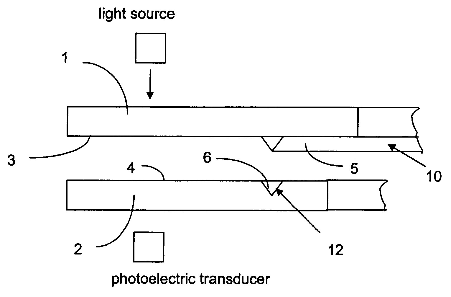
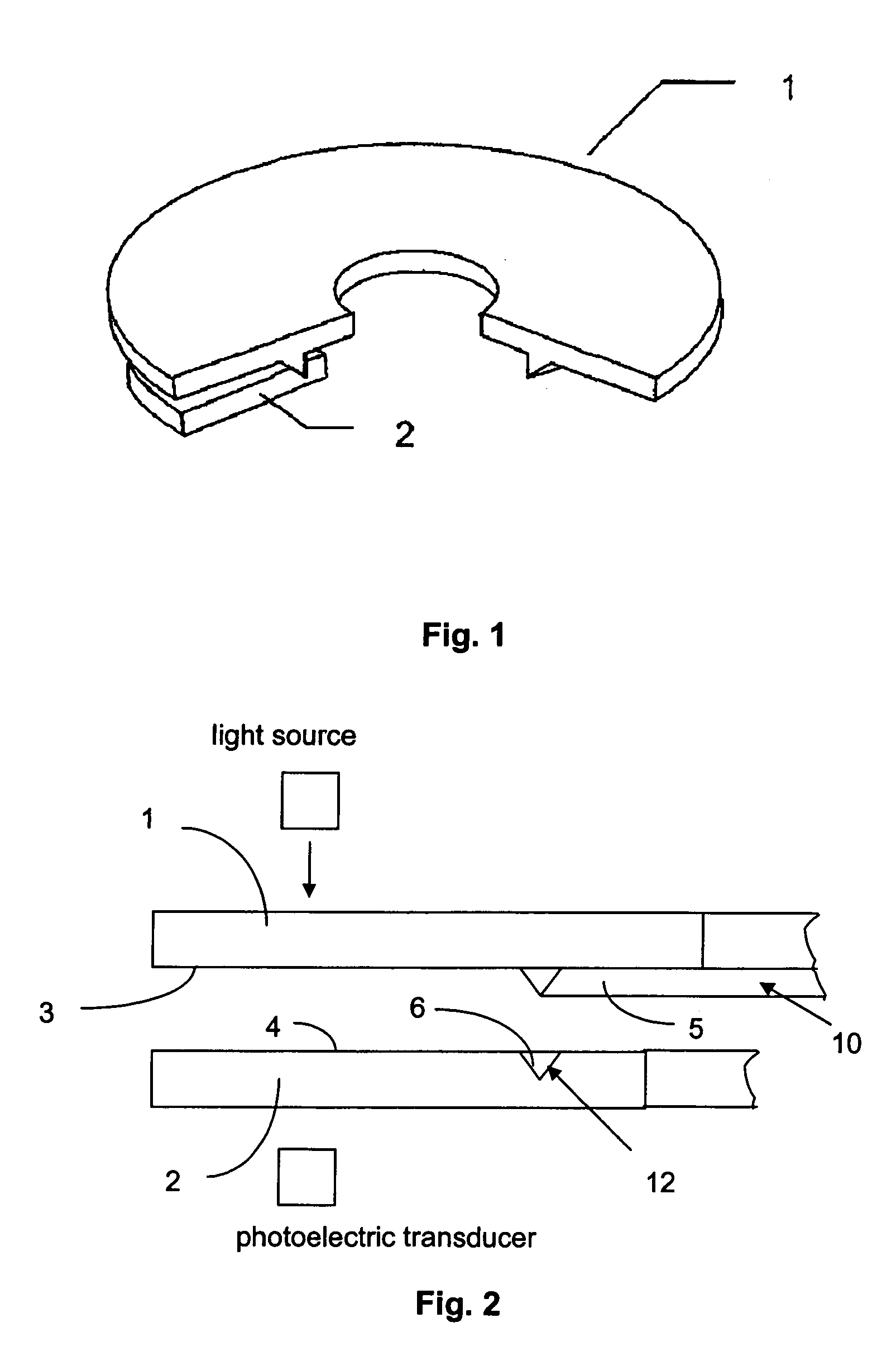
[0024]A rotary angle sensor according to the invention has a first measurement member 1 that is able to move in a measurement direction and a second, static measurement member 2. By measuring the motion of measurement member 1 relative to the measurement member 2, a rotary angle can be determined, as has long been known.

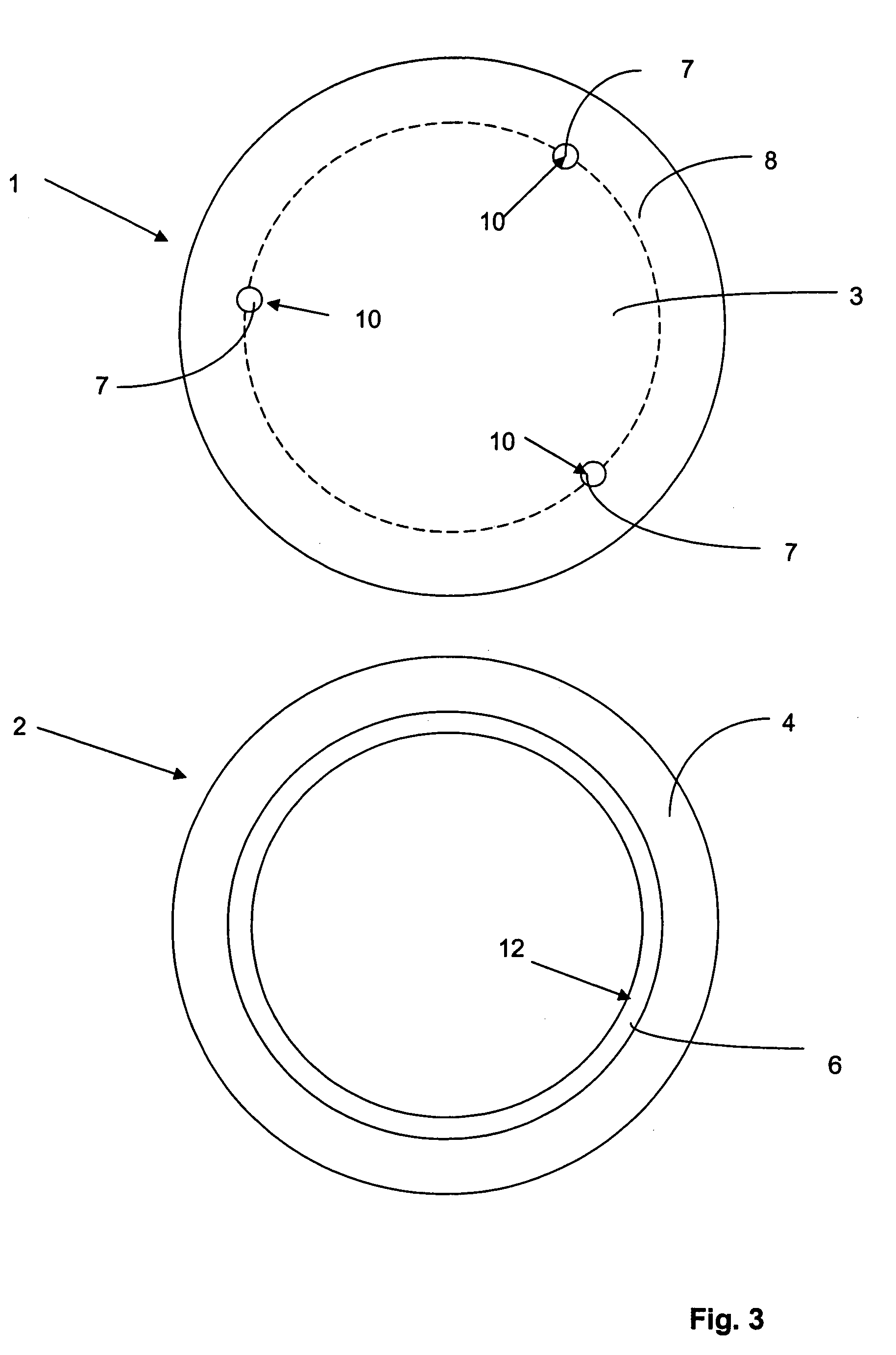
[0025]According to the invention, the measurement members 1 and 2 lie with a certain spacing on top of each other, a bottom side 3 of the first measurement member 1 being opposite a top side 4 of the second measurement member 2. To assure that measurement members 1 and 2 are concentric to each other in every angular position and independently of any shaft bearing, a guide between measurement members 1 and 2 maintains them concentric with respect to each other.

[0026]The guide consists of a guide element 10 projecting from bottom side 3 of the first measurement member 1 and a guide recess 12 provided on top side 4 of the second measurement member 2, in which the guide ...


PUM


Abstract

An optical rotary angle sensor with at least one first measurement member able to move in the measuring direction having light-transparent and non-transparent regions located on it, at least one second measurement member arranged static relative to the first measurement member in the measuring direction, and / or at least one photoelectric transducer. To keep the distance between the rotating measurement member and the static measurement member and / or the optical-electrical transducer very small, i.e. in the range of about 10–20 μm, and to make the centering of the two relative to each other independent of the formerly necessary shaft bearing, the measurement members are configured so that they are properly oriented relative to each other in the measuring direction and kept spaced apart by a guide provided between the measurement members. The guide can be a form-fitting connection in at least one of the directions not representing the measurement direction.

Description

BACKGROUND OF THE INVENTION[0001]The invention concerns an optical sensor for determining angles of rotation.[0002]Such optical systems all work on the principle of the object to be measured moving in a measurement direction relative to a stationary scanning system. Measurements concerning the object are then processed as light and directed onto electrical photoreceivers.[0003]One commonly used principle for operating such optical systems is the transmitted light principle, in which the object, which could be made of glass, transparent plastic, or metal with light-transparent structures etched out, is penetrated by light, preferably parallel light. On the opposite side, the light which has been modulated by the movement of the object is transformed by photoreceivers into electrical signals. This method is relatively simple and economical to carry out.[0004]Another principle used for such optical sensors is optically scanning the object for light reflected by it. Less common, because...

Claims


Application Information

Patent Timeline
Patent Type & Authority Patents(United States)
IPC IPC(8): G01B11/26G01D5/347G01D11/02
CPCG01D11/02G01D5/34707
Inventor SIRAKY, JOSEF
Owner SICK STEGMANN
Why Eureka
Try Eureka