
Fuel injector having external setting of the coil spring

Active Publication Date: 2018-07-19
DELPHI TECH IP LTD
View PDF0 Cites 0 Cited by
  • Summary
  • Abstract
  • Description
  • Claims
  • Application Information

AI Technical Summary

Benefits of technology

The present invention proposes a simple and economical solution to overcome the disadvantages of prior art. Specifically, the invention provides a body with a radial hole through which an adjusting tool can be passed to move the adjusting member in a coil assembly. This allows for the adjustment of the fuel flow within a predefined tolerance range. The technical effects of this invention include improved accuracy and efficiency in adjusting the fuel flow and reduced complexity and cost compared to prior art solutions.

Problems solved by technology

However, this possibility has these technical limits, and the width of the current tolerance range is at the expense of improving the production quality of the injectors.

Method used


Image

  • Fuel injector having external setting of the coil spring
  • Fuel injector having external setting of the coil spring
  • Fuel injector having external setting of the coil spring

Examples


first embodiment

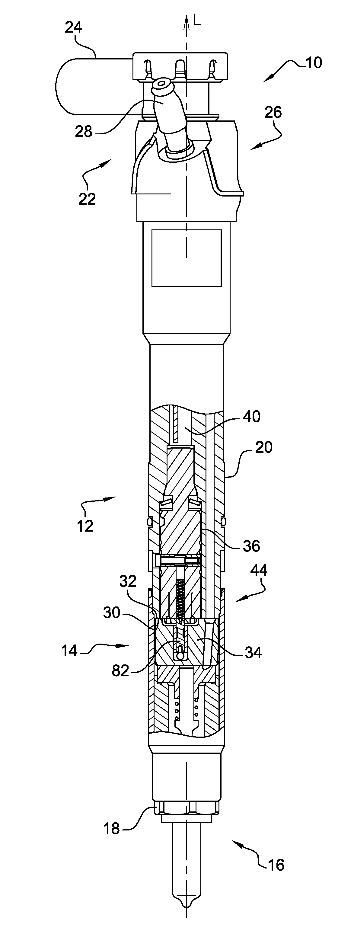
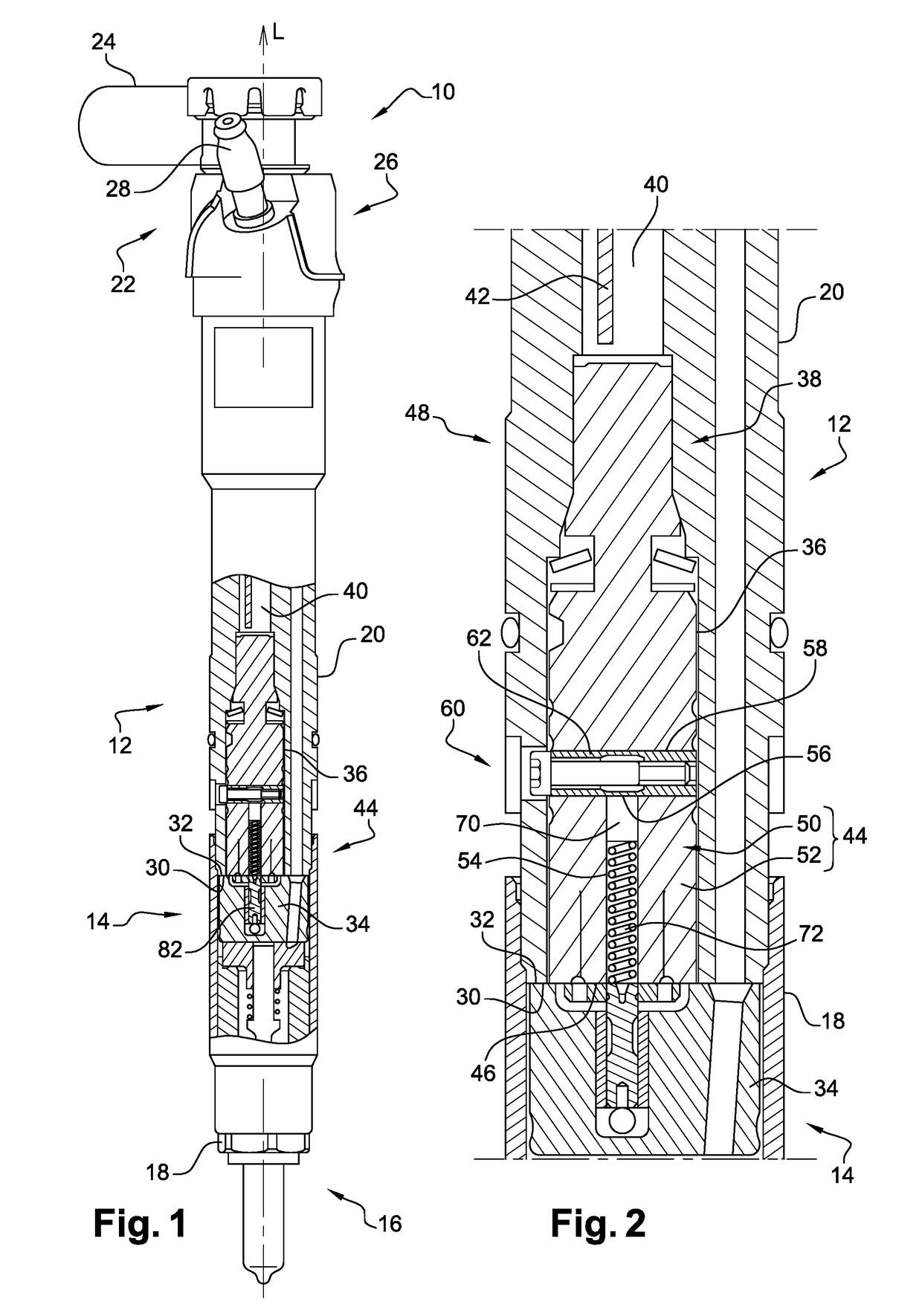
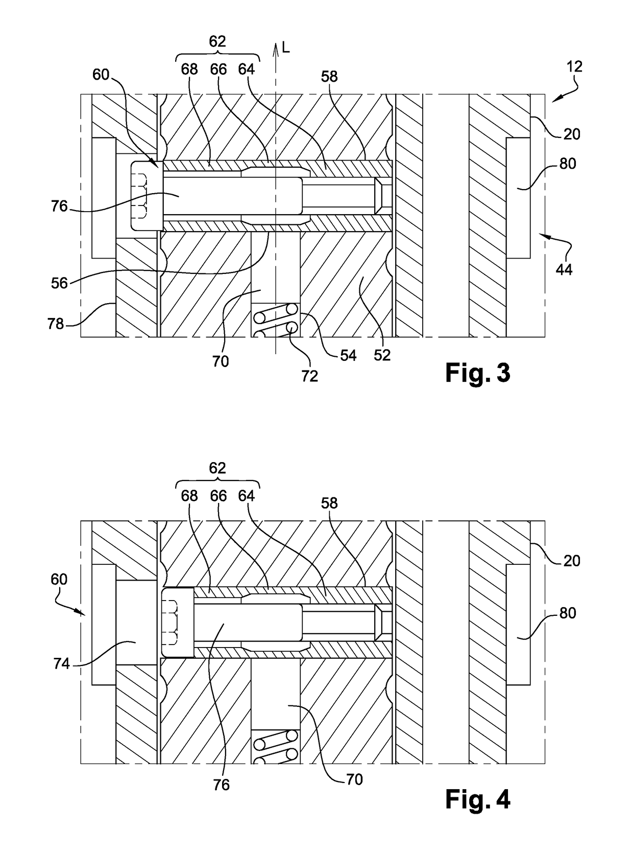
[0032]An adjusting member 62 is arranged in the radial bore 58, which adjusting member, shown in FIGS. 1, 2 and 3, is a revolution-generated cylindrical tubular piece fitted into the radial bore 58, the external diameter of the adjusting member 62 and the diameter of the radial bore 58 being almost identical. The adjusting member 62 has a length substantially equal to that of the bore extending between the two openings 60, or between the bottom of the bore 58, if this is a blind bore, and the single opening 60.

[0033]The adjusting member 62 comprises a fixed part 64, arbitrarily shown on the right in the figure, and fixed for example by gluing in the radial bore 58. This fixed part is inwardly threaded and therefore resembles a nut. In the center of the adjusting member 58, the wall is thinned with respect to that of the fixed part 64 with the aim of forming a deformable part 66 with less mechanical strength. Finally, shown on the left of the figure and extending between the deforma...

second embodiment

[0047]the adjusting member 62 is now described with reference to FIG. 5. The general principle remains the same but, in this case, the adjusting member 62 comprises two separate parts.

[0048]Shown on the right in FIG. 5, a first piece incorporates the fixed 64 and deformable 66 parts. This inwardly threaded tubular part is fixed in the radial bore 58 and extends from between an opening 60 of said bore, or from the bottom of the radial bore if the latter is a blind bore, and the center of the bore where this first piece blocks the bottom of the longitudinal bore 54. The end blocking the bottom of the longitudinal bore 54 is the deformable part 66 of the adjusting member 62. It is produced as a bevel, the internal threading being shorter than the external cylindrical face, the face joining said threading to said outer cylindrical face is a female conical face 84, the apex of which is located in the first piece.

[0049]The adjusting member 62 comprises a second piece which is, in fact, a ...

third embodiment

[0052]Whether for the second or the third embodiment, the alternative consisting in shortening the outer part in order to make the adjusting screw head enter the radial bore, as shown in FIG. 4, is, of course, possible.

[0053]According to an alternative that is not shown, there is nothing to prevent the longitudinal axis from not being perpendicular to the longitudinal axis.


PUM


Abstract

A coil assembly includes an electric coiling included in an overmold, the coiling being suitable to drive the control valve of a fuel injector. The coil assembly is provided with a longitudinal bore suitable for receiving a spring and with an adjusting member for the setting of the spring which can be moved from outside the injector, the adjusting member forming a transfer of movement such that the movement of the adjusting member from outside the injector is transformed into a compression of the spring.

Description

CROSS REFERENCE TO RELATED APPLICATIONS[0001]This application is a national stage application under 35 USC 371 of PCT Application No. PCT / EP2016 / 065206 having an international filing date of Jun. 29, 2016, which is designated in the United States and which claimed the benefit of FR Patent Application No. 1556494 filed on Jul. 9, 2015, the entire disclosures of each are hereby incorporated by reference in their entirety.TECHNICAL FIELD[0002]The present invention relates to a fuel injector and more particularly an adjusting device for the setting of the valve spring with which it is provided.TECHNOLOGICAL BACKGROUND OF THE INVENTION[0003]In a fuel injector, a solenoid control valve makes it possible to drive the movements of an injection needle via the variation of the pressure in a control chamber in which the head of the needle is located. When the solenoid valve is powered, it generates a magnetic field which attracts a magnetic core rigidly connected to a control valve slide, thus...

Claims


Application Information

Patent Timeline
IPC IPC(8): F02M61/20F02M47/02F02M63/00
CPCF02M61/205F02M47/027F02M63/0017F02M2200/505F02M61/18F02M61/1806
Inventor LEROUX, LUDOVICTHIBAULT, THIERRY
Owner DELPHI TECH IP LTD
Learn More