
Torque wrench with torque range indicator and system and method employing the same

a torque range indicator and torque wrench technology, applied in the field of hand tools, can solve the problems of thread slipping, insufficient accuracy of the device, and insufficient torque values, etc., and achieve the effect of reducing the number of times of use, and reducing the accuracy of the devi

Active Publication Date: 2006-08-15
RYESON CORP
View PDF17 Cites 72 Cited by
  • Summary
  • Abstract
  • Description
  • Claims
  • Application Information

AI Technical Summary

Benefits of technology

"The patent describes a torque wrench with a programmable interface module that can adjust the amount of force applied to a screw or bolt. The module includes a torque sensor and a controller that compares the measured torque value to a predetermined value and activates the torque range indicator accordingly. This allows for easier and more precise tightening of screws or bolts. The technical effect of this invention is to provide a more efficient and effective tool for tightening screws and bolts."

Problems solved by technology

Moreover, it is not sufficient that the device simply be tightened as far as possible as this may result in stripping of the threads or vibrational problems in the resulting assembly.
However, such a device is normally not sufficiently accurate for the specifications being set forth by the automotive and aircraft industries which commonly employ such devices.
However, all currently known torque wrenches suffer from certain drawbacks resulting in less than optimal torque values and / or require an inordinate amount of time to use properly.
For example, as the operator is rotating a fastener it becomes difficult for the operator to continue torquing the fastener while at the same time having to read the actual torque value on the torque value display.

Method used


Image

  • Torque wrench with torque range indicator and system and method employing the same
  • Torque wrench with torque range indicator and system and method employing the same
  • Torque wrench with torque range indicator and system and method employing the same

Examples


Embodiment Construction

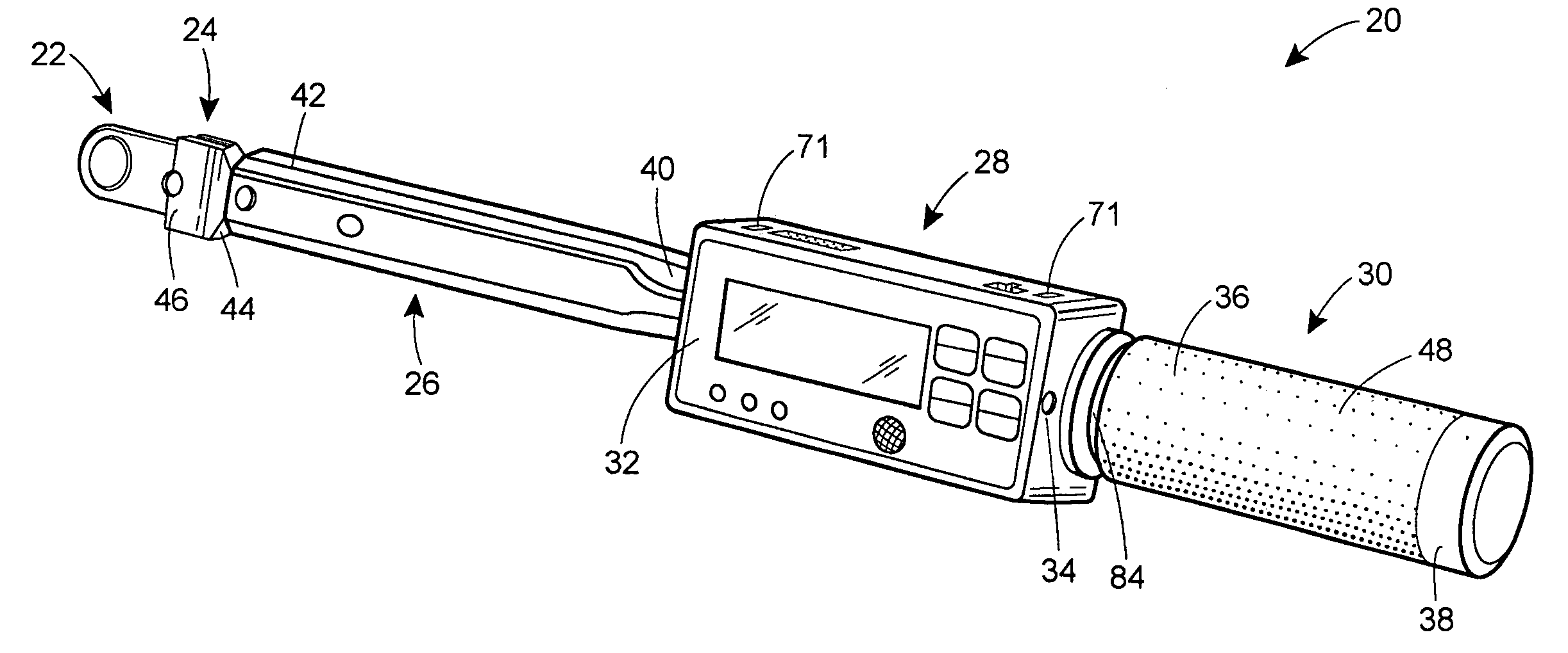
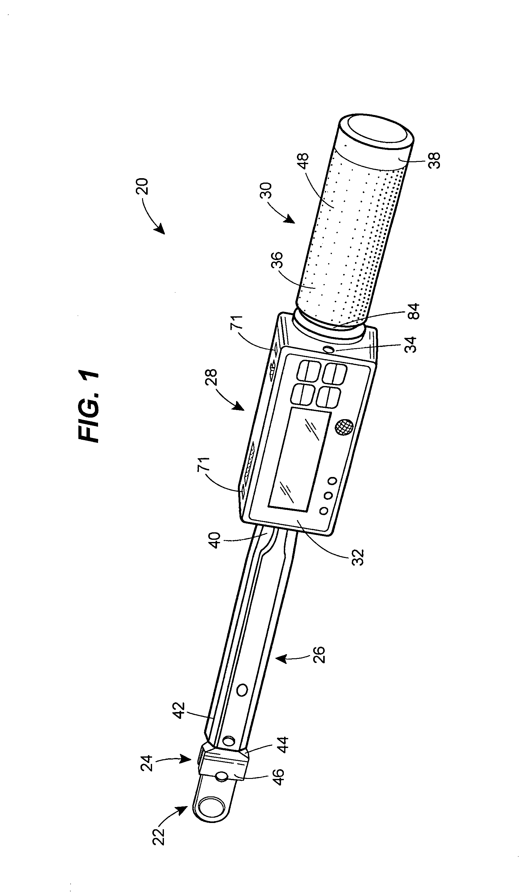
[0019]Turning now to the drawings, and with specific reference to FIG. 1, a torque wrench constructed in accordance with the teachings of the disclosure is generally referred to by reference numeral 20. As shown therein, the torque wrench 20 is of the type adapted to rotate a threaded fastener to a predetermined torque value. The torque wrench 20 may further be adapted to indicate an actual torque value, and may be adapted to indicate a torque range based on the actual torque value and the predetermined torque value. Such high quality, accurate wrenches are particularly applicable for use in tightly toleranced assembly processes including those of the automotive and aircraft industries. Moreover, while the torque wrench 20 is described and depicted as being a digital torque wrench, it is to be understood that its teaching could be employed for creating an analog output as well.

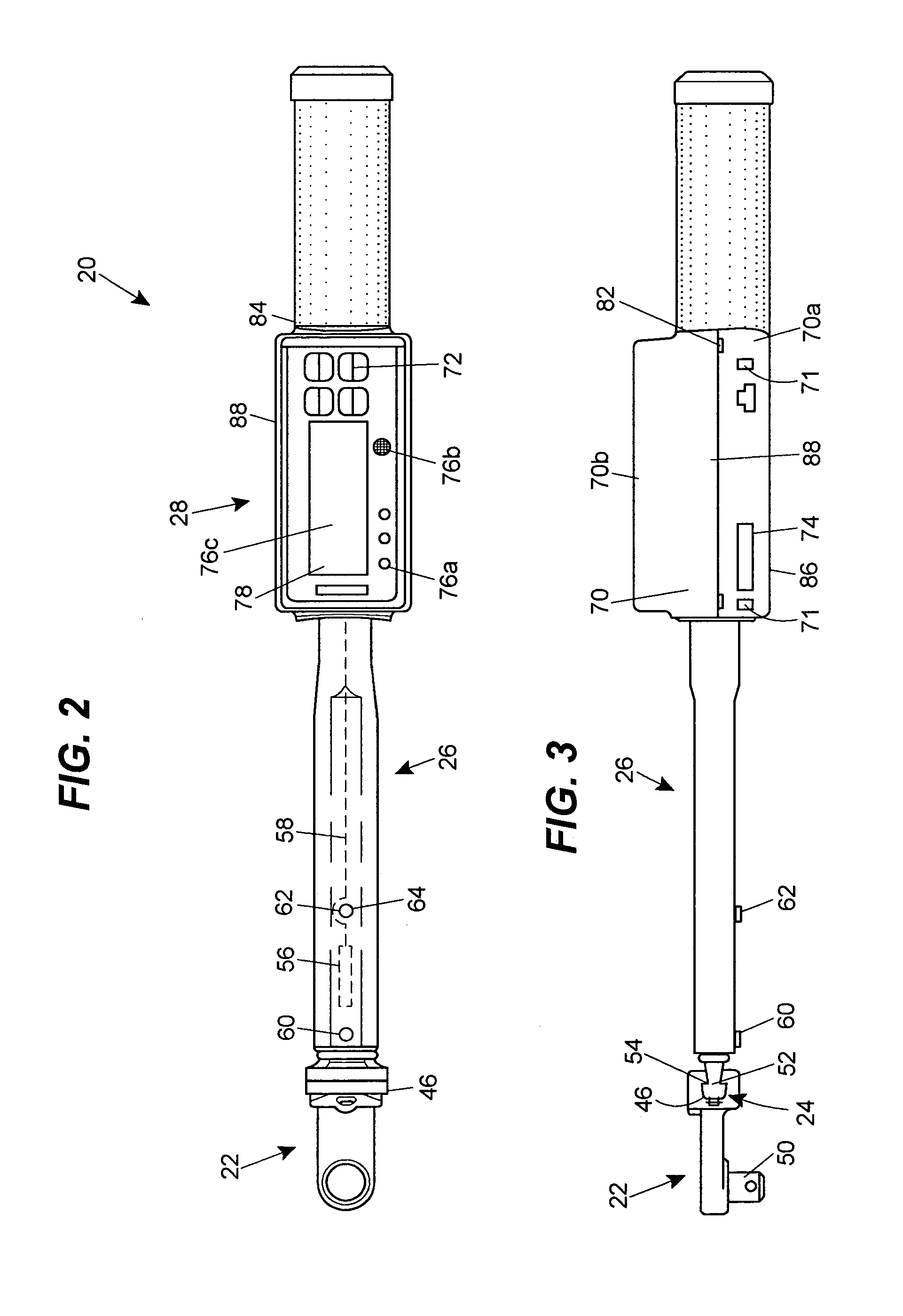
[0020]Referring now to FIGS. 1–3, the torque wrench 20 is shown to include a torquing tool 22, a transducer...


PUM

PropertyMeasurementUnit
torqueaaaaaaaaaa
coloraaaaaaaaaa
shearing stressaaaaaaaaaa

Abstract

A torque wrench is disclosed having torque range indicators. The torque wrench includes a handle, a torquing tool, a mounting bar and a programmable interface module. At least one torque sensor is communicatively coupled to the interface module. The interface module includes an input device able to receive at least one predetermined torque value, a torque value indicator, a torque range indicator, and a controller. The torque value indicator, the torque sensor, and the torque range indicator are communicatively coupled to the controller, and the controller is programmed to activate the torque range indicator based on a torque range calculated by comparing a torque value received from the torque sensor to the at least one predetermined torque value.

Description

FIELD OF THE DISCLOSURE[0001]The disclosure generally relates to hand tools and, more particularly, relates to torque wrenches.BACKGROUND OF THE DISCLOSURE[0002]In many industrial applications, the tightening of threaded fasteners to a specific degree or torque is of extreme importance. For example, in the assembly of automobiles or aircraft, it is imperative that nuts, bolts, screws, lugs, and the like, are tightened to a pre-specified torque to ensure the resulting assembly functions properly not only at initial use, but over the long term. Moreover, it is not sufficient that the device simply be tightened as far as possible as this may result in stripping of the threads or vibrational problems in the resulting assembly.[0003]Accordingly, it has long been known to use torque wrenches for tightening such devices. Such wrenches are not only able to rotate and tighten the device, but also provide the user with some sort of indication as to exact torque being applied. Such devices can...

Claims


Application Information

Patent Timeline
Patent Type & Authority Patents(United States)
IPC IPC(8): B25B23/144B25B23/159G01D1/14G01L5/24B25B23/14B25B23/142
CPCB25B23/1425B25B23/14
Inventor REYNERTSON, JOHNGAUTHIER, JEROME M.
Owner RYESON CORP
Learn More