
Methods and apparatus for reforming and expanding tubulars in a wellbore

a wellbore and tubular body technology, applied in the direction of drilling casings, wellbore/well accessories, pipes, etc., can solve the problems of limited expansion of casing strings, limiting the volume of hydrocarbon production of casing strings, and reducing the diameter of wellbores, etc., to achieve the effect of expanding the inner diameter of casing strings

Inactive Publication Date: 2006-08-15
WEATHERFORD TECH HLDG LLC
View PDF91 Cites 27 Cited by
  • Summary
  • Abstract
  • Description
  • Claims
  • Application Information

AI Technical Summary

Benefits of technology

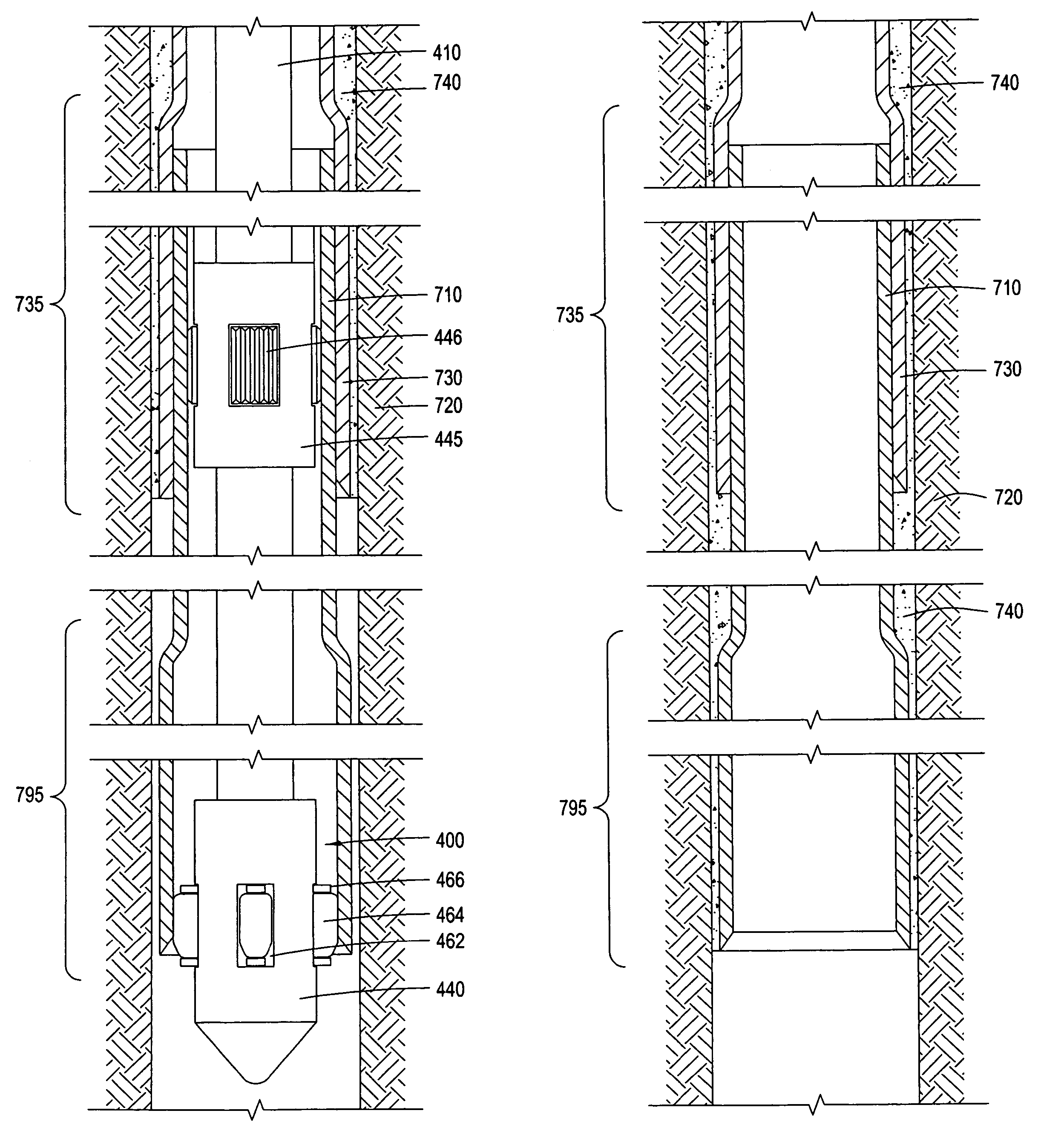
[0021]The present invention advantageously provides a method for enlarging the inner diameter of a casing string by more than about 22–25% without compromising the structural integrity of the casing string. Further, the present invention provides a method for expanding the inner diameter of a casing string further than the allowed elastic limit after running the casing string through a restricted inner diameter portion of the wellbore. The present invention also allows a method of expanding a lower portion of the inner diameter of a casing string further than the remaining portions of the casing string without compromising the structural integrity of the lower portion of the casing string.

Problems solved by technology

Decreasing the diameter of the wellbore produces undesirable consequences.
Furthermore, restricting the inner diameter of the casing strings limits the volume of hydrocarbon production which may flow to the surface from the formation.
Because a casing string is typically only capable of expansion to about 22–25% past its elastic limit, the amount of expansion of the casing string is limited when using this method.
Expansion past about 22–25% of its original diameter may cause the casing string to fracture due to stress.
Certain problems have arisen during the investigation of monobore wells.
One problem relates to the expansion of the smaller casing string into the larger casing string to form a sealed connection therebetween where the first and second casing strings overlap.
In this way, expansion of the casing string to over 25% of its original diameter would be necessary, but not currently possible.
Merely expanding the casing string past its elastic limit after passing the restricted inner diameter portion may not allow the casing string to expand to a large enough inner diameter to form a substantially monobore well, as the percentage which the casing string may expand past its elastic limit is limited by structural constraints of the casing string.
Attempts to expand the casing string further than about 22–25% past its elastic limit may cause the casing string to fracture or may simply be impossible.
This method often leaves stress lines in the reformed casing patch where the corrugations originally existed, weakening the casing patch at the stress lines so that the casing patch is susceptible to leaking wellbore fluids into the casing patch due to the pressure exerted by wellbore fluids.
Utilizing the current methods of expanding a casing string or reforming a casing patch, the problems described above are evident when a casing string or casing patch must run through a restriction in the inner diameter of the wellbore, such as a restriction formed by a packer or a previously installed casing patch, and then expand to an inner diameter at least as large as the restriction once the casing string or casing patch is lowered below the restriction.
When using a casing patch, merely reforming the casing patch may leave stress lines in the casing patch which may allow fluid leakage therethrough.
When using a casing string, merely expanding the casing string past its elastic limit by 22–25% may not allow enough expansion to increase the inner diameter of the casing string to at least the inner diameter of the restriction.

Method used


Image

  • Methods and apparatus for reforming and expanding tubulars in a wellbore
  • Methods and apparatus for reforming and expanding tubulars in a wellbore
  • Methods and apparatus for reforming and expanding tubulars in a wellbore

Examples


Embodiment Construction

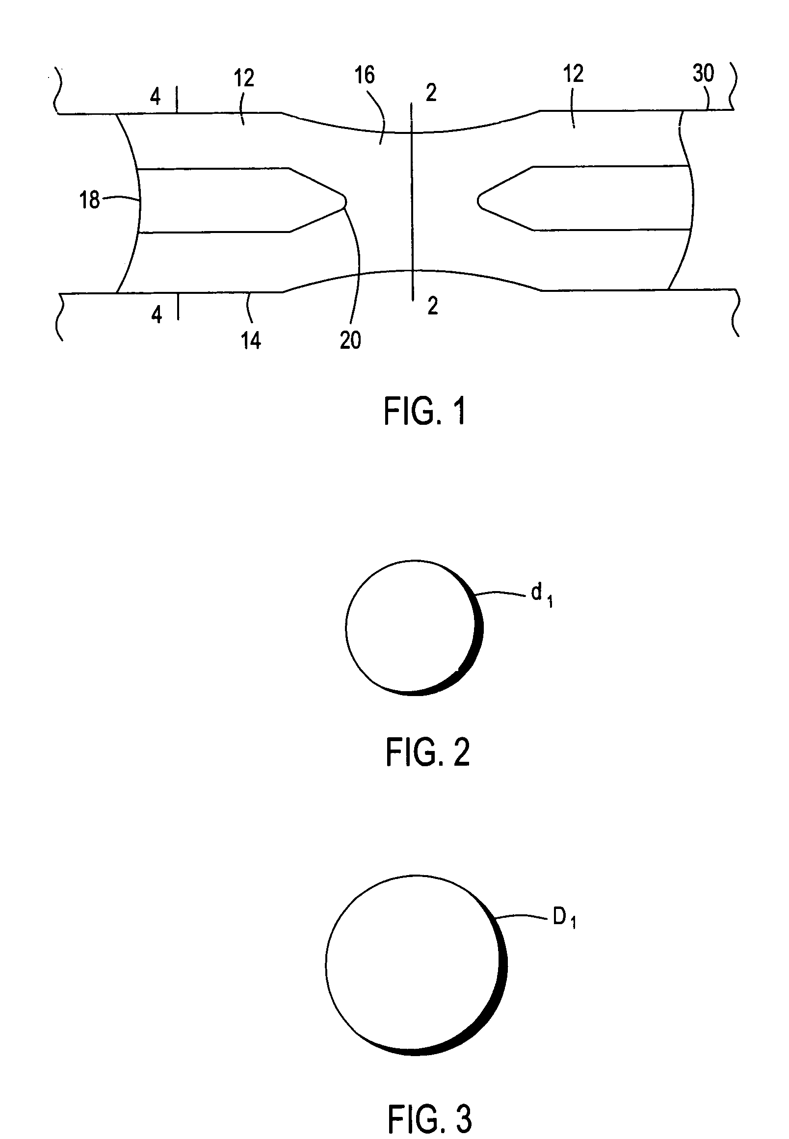
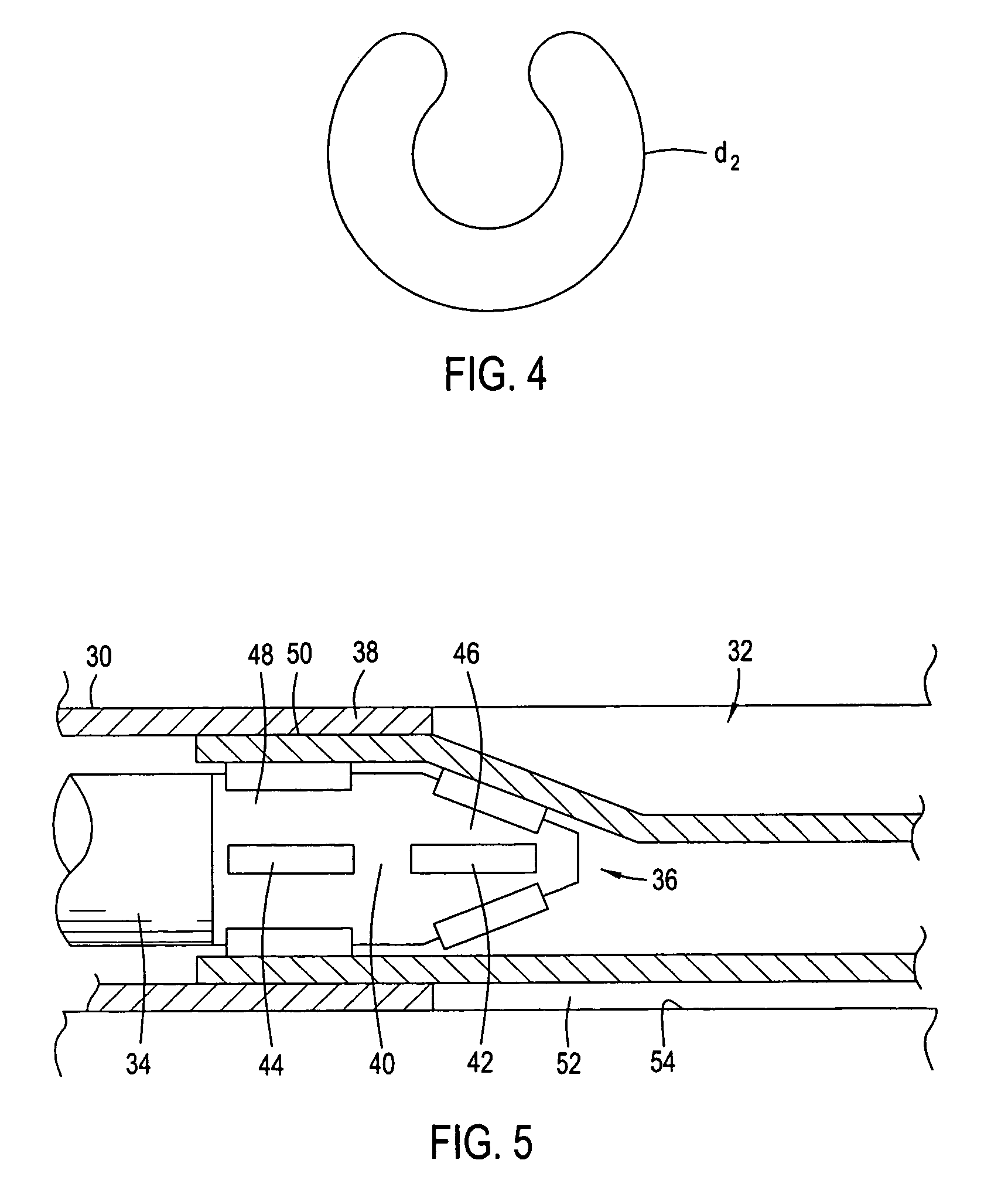
[0044]It is among the objectives of embodiments of the present invention to facilitate use of folded tubing in downhole applications, and in particular to permit use of tubing made up from a plurality of folded pipe sections which may be coupled to one another at surface before being run into the bore.

[0045]According to a first aspect of the present invention there is provided downhole apparatus comprising a plurality of tubing sections, each tubing section having substantially cylindrical end portions initially of a first diameter for coupling to end portions of adjacent tubing sections and being expandable at least to a larger second diameter, and intermediate folded wall portions initially in a folded configuration and being unfoldable to define a substantially cylindrical form at least of a larger third diameter.

[0046]The invention also relates to a method of lining a bore using such apparatus. Thus, the individual tubing sections may be coupled together via the end portions to ...


PUM


Abstract

The present invention provides a method and apparatus for deforming a tubular body, running the tubular body through a restriction in a wellbore, reforming the tubular body, and expanding at least a portion of the tubular body past its elastic limit. In one aspect, the present invention provides a method for forming a substantially monobore well involving deforming a tubular body, running the tubular body below a restricted inner diameter portion, reforming the tubular body, and expanding at least a portion of the tubular body past its elastic limit. The restricted inner diameter portion may comprise a casing string previously disposed within the wellbore or a casing patch. The at least the portion of the tubular body expanded past its elastic limit may be a lower portion of the tubular body. Subsequent tubular bodies may be reformed and expanded below previous tubular bodies.

Description

CROSS-REFERENCE TO RELATED APPLICATIONS[0001]This application is a continuation-in part of U.S. patent application Ser. No. 10 / 032,998, filed on Oct. 25, 2001, now U.S. Pat. No. 6,708,767 which is herein incorporated by reference in its entirety. U.S. patent application Ser. No. 10 / 032,998 claims benefit of Great Britain Application Serial Number 0026063.8, filed on Oct. 25, 2000, which is herein incorporated by reference in its entirety.[0002]This application further claims benefit of U.S. Provisional Application No. 60 / 467,503, filed on May 2, 2003, which is herein incorporated by reference in its entirety.BACKGROUND OF THE INVENTION[0003]1. Field of the Invention[0004]The present invention generally relates to methods and apparatus for expanding a tubular body in a wellbore. More specifically, the invention relates to methods and apparatus for forming a cased wellbore having an inner diameter that does not decrease with increasing depth within a formation.[0005]2. Description of ...

Claims


Application Information

Patent Timeline
Patent Type & Authority Patents(United States)
IPC IPC(8): E21B23/02E21B43/10
CPCE21B43/103E21B43/105E21B43/106E21B43/10
Inventor HAUGEN, DAVIDHARRALL, SIMON JOHNMETCALFE, PAUL DAVIDTILTON, FREDERICK T.
Owner WEATHERFORD TECH HLDG LLC
Learn More