Imaging arrangement and barcode imager for imaging an optical code or target at a plurality of focal planes

a barcode imager and optical code technology, applied in the field of imaging, can solve the problems of inconvenient maintenance, high cost of imaging arrangements, and inability to compete well with laser-based barcode readers,

Active Publication Date: 2006-08-15
SYMBOL TECH LLC
View PDF18 Cites 140 Cited by
  • Summary
  • Abstract
  • Description
  • Claims
  • Application Information

AI Technical Summary

Benefits of technology

[0011]The imaging arrangement and barcode imager of the present invention achieve these and other aspects by providing an extended working range (i.e., greater than 61 cm or 24 inches) of approximately 5–102 cm (˜2–40 inches) compared to a typical working range of approximately 5–61 cm (˜2–24 inches) for conventional barcode imagers. The imaging arrangement and image-based barcode imager of the present invention do not require complex automatic-focusing systems. As such, the performance of the image-based one-dimensional barcode imager of the present invention in imaging and decoding one-dimensional barcode symbols (and in imaging and processing labels, markings, pictures, etc.) is comparable to or even greater than conventional laser-based barcode readers and image-based barcode imagers.

Problems solved by technology

However, the operator is still required to position the imaging device within the proper range to produce an adequately sharp, i.e. substantially focused image; this may require a trial and error approach on the part of the operator in order to obtain the proper distance from the target to be imaged.
In many applications where an increased working range is necessary, expensive and complex imaging arrangements having state-of-the-art automatic focus systems, such as zoom capabilities, are generally incorporated within or used in conjunction with barcode imagers to increase their working range.
However, such imaging arrangements, besides being expensive, generally require constant maintenance.
Therefore, when an application calls for imaging and decoding one-dimensional barcode symbols, these imaging arrangements do not compete well in the marketplace against laser-based barcode readers which have comparable or even greater working ranges, and generally are less expensive.

Method used


Image

  • Imaging arrangement and barcode imager for imaging an optical code or target at a plurality of focal planes
  • Imaging arrangement and barcode imager for imaging an optical code or target at a plurality of focal planes
  • Imaging arrangement and barcode imager for imaging an optical code or target at a plurality of focal planes

Examples


first embodiment

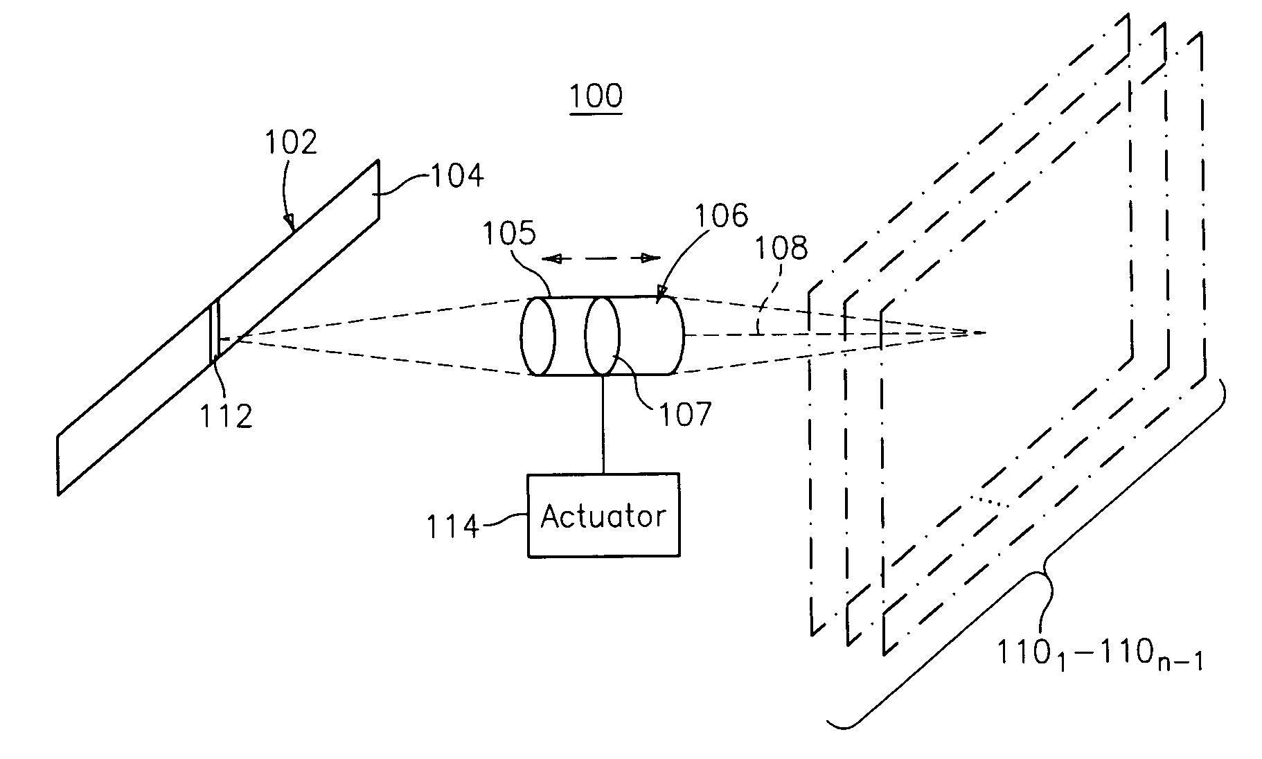
[0019]With reference to FIG. 1, an imaging arrangement according to a first embodiment of the present invention is shown and designated generally by reference numeral 100. The imaging arrangement 100 includes an image sensor 102 having a one-dimensional, solid-state image sensor array 104, and a lens assembly 106. The lens assembly 106 includes a carrier 105 housing at least one objective lens 107.

[0020]The carrier 105 is moveable along an optical axis 108 of the imaging arrangement 100 by an actuator 114 for enabling the at least one objective lens 107 to focus an optical code or target, such as a one-dimensional barcode symbol, having a plane transverse to the optical axis 108 and correlated in space to one of a plurality of focal planes 1101–110n−1, onto the image sensor 102. Movement of the carrier 105 is illustrated by the two arrows shown in FIG. 1. In the alternative, it is contemplated that only the at least one objective lens 107 within the carrier 105 of the lens assembly ...

second embodiment

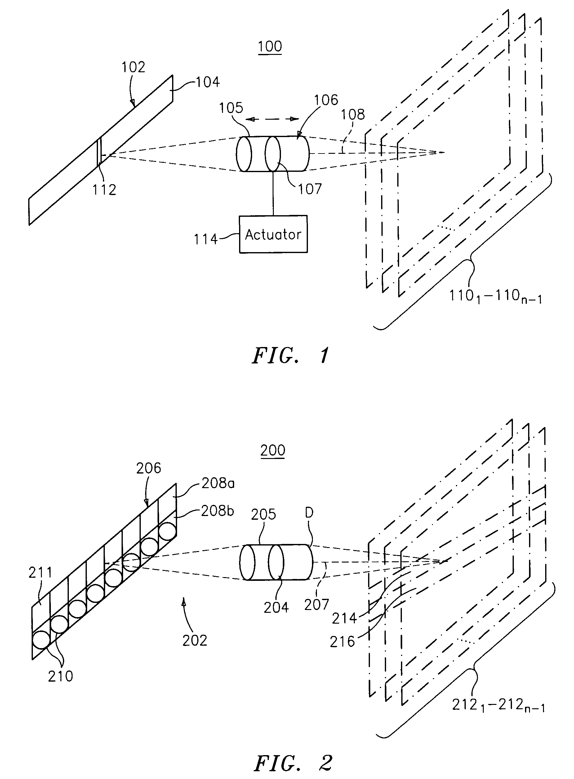
[0039]FIG. 2 illustrates another embodiment of an imaging arrangement in accordance with the present invention and designated generally by reference numeral 200. In this embodiment, a lens assembly 202 includes at least one objective lens 204. The lens assembly 202 includes a carrier 205 housing the at least one objective lens 204. The carrier 205 is fixed at a predetermined distance with respect to an image sensor 206, and positioned along the optical axis 207 of the imaging arrangement 200. This embodiment does not have any moveable components.

[0040]The image sensor 206 is a two-dimensional image sensor 202, and preferably, a 2×1024 image sensor 202. That is, the image sensor 206 includes two one-dimensional image sensor arrays 208a, 208b each having one pixel row. In an alternate embodiment, the imaging arrangement 200 includes two one-dimensional image sensors as image sensor 102 which are stacked to resemble one two-dimensional image sensor.

[0041]The lens assembly 202 further i...

third embodiment

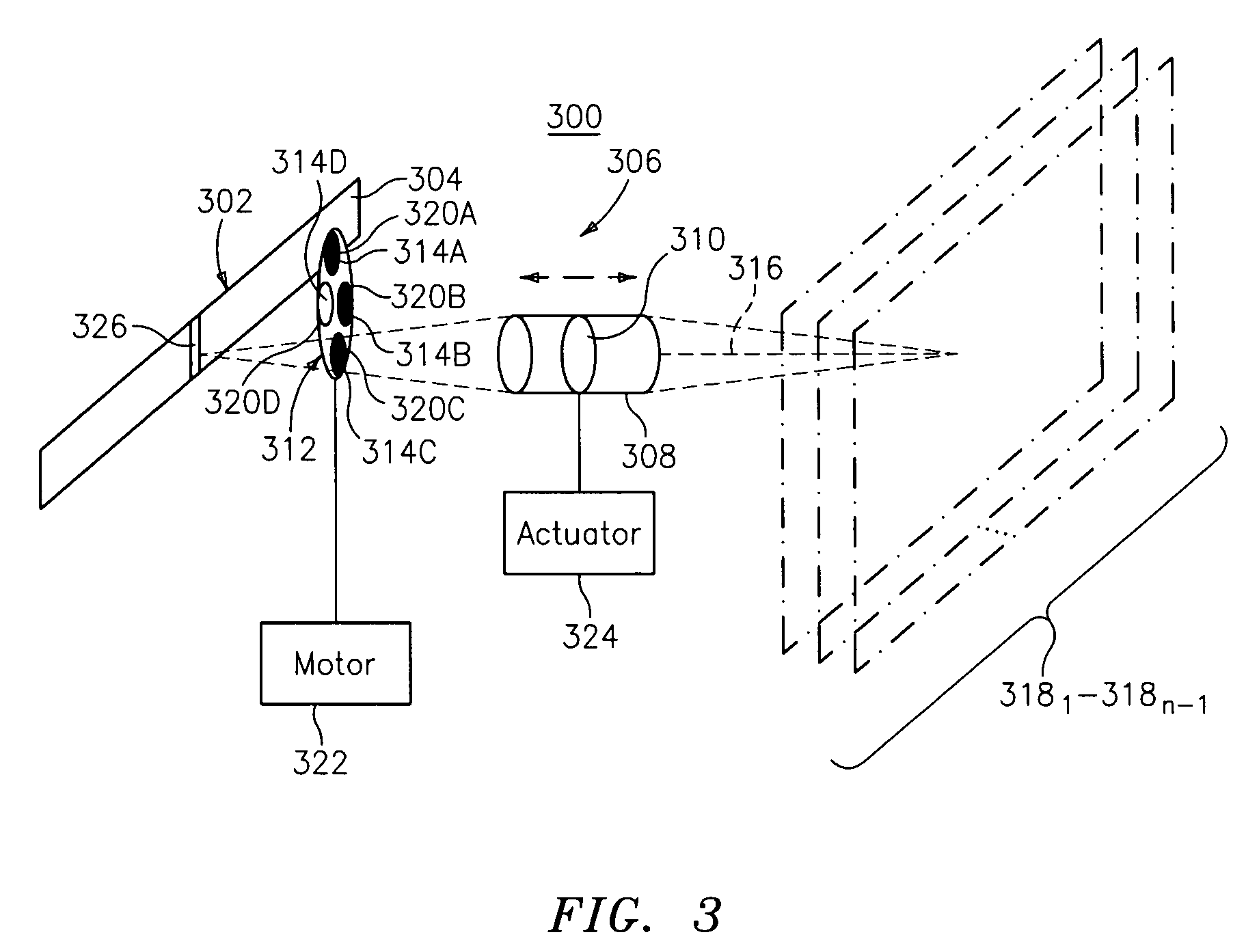
[0063]With reference to FIG. 3, an imaging arrangement according to a third embodiment of the present invention is shown and designated generally by reference numeral 300. The imaging arrangement 300 includes an image sensor 302 having a one-dimensional, solid-state image sensor array 304, and a lens assembly 306. The lens assembly 306 includes a first carrier 308 housing at least one objective lens 310 and a second carrier 312 having a plurality of segments 314A–D. This embodiment is similar to the first embodiment with the addition of the second carrier 312.

[0064]The first carrier 308 is moveable along an optical axis 316 of the imaging arrangement 300 for enabling the at least one objective lens 310 to focus an optical code or target, such as a one-dimensional barcode symbol, through one of the plurality of segments 314A–D onto the image sensor array 304. The optical code or target has a plane transverse to the optical axis 316 and correlated in space to one of a plurality of foc...


PUM


Abstract

Three non-complex imaging arrangements are provided where in two of the imaging arrangements a moveable carrier housing at least one objective lens is provided and, in the other imaging arrangement, at least one stationary objective lens and additional optical elements are provided. Each embodiment includes at least one fixed image sensor array for imaging thereon an optical code or target, such as a one-dimensional barcode symbol, or label, marking, picture, etc. Each imaging arrangement provides an extended working range of approximately 5–102 cm. The imaging arrangements are capable of being incorporated within a barcode imager to provide a non-complex barcode imager having an extended working range which is comparable to or greater than the working ranges of conventional image-based barcode imagers.

Description

PRIORITY[0001]The present application claims priority to a U.S. Provisional Application filed on Jul. 7, 2003 and assigned U.S. patent application Ser. No. 60 / 485,184, the contents of which are incorporated herein in their entirety.BACKGROUND OF THE INVENTION[0002]1. Field of the Invention[0003]The present invention relates to the field of imaging, and specifically to an imaging arrangement and barcode imager for imaging an optical code or target at a plurality of focal planes.[0004]2. Description of the Related Art[0005]CCD or CMOS-based imaging devices, such as conventional barcode imagers, generally have limited working ranges on the order of 5–61 cm (˜2–24 inches). In many cases, these imaging devices are designed to be handheld or at least moveable within a given area, thus compensating, somewhat, for the limited working range. However, the operator is still required to position the imaging device within the proper range to produce an adequately sharp, i.e. substantially focuse...

Claims


Application Information

Patent Timeline
Patent Type & Authority Patents(United States)
IPC IPC(8): G06K7/10
CPCG06K7/10811
Inventor PATEL
Owner SYMBOL TECH LLC
Why Eureka
Try Eureka