Projector

a projector and optical system technology, applied in the field of projectors, can solve the problems of increasing the size of the casing, unable to figure out whether the projection optical system is moved up or down, and the gap may leak light, etc., and achieve the effect of easy recognition

Inactive Publication Date: 2006-08-15
SEIKO EPSON CORP
View PDF11 Cites 37 Cited by
  • Summary
  • Abstract
  • Description
  • Claims
  • Application Information

AI Technical Summary

Benefits of technology

[0010]Exemplary embodiments of the present invention provide a projector having a projection optical system position adjuster that enables a user to easily recognize a moving direction of a projection optical system.
[0011]Exemplary embodiments of the present invention provide a projector that can securely reduce or prevent a light beam from leaking, and also reduce or prevent increase of a size of a casing thereof.

Problems solved by technology

However, in such a projection optical system position adjuster, since a rotary direction of the knob and a moving direction of the projection optical system are not correspondent, it is difficult to figure out whether the projection optical system is moved up or down, which is a first problem.
Accordingly, the length of the casing in the moving direction of the projection lens might be increased, thus increasing the size of the casing, which is a second problem.
Furthermore, when the two shield plates are used, a gap is generated at a part where the two shield plates are layered, and a light may leak from the gap, which is a third problem.

Method used


Image

  • Projector
  • Projector
  • Projector

Examples


first exemplary embodiment

(1) Exterior Arrangement

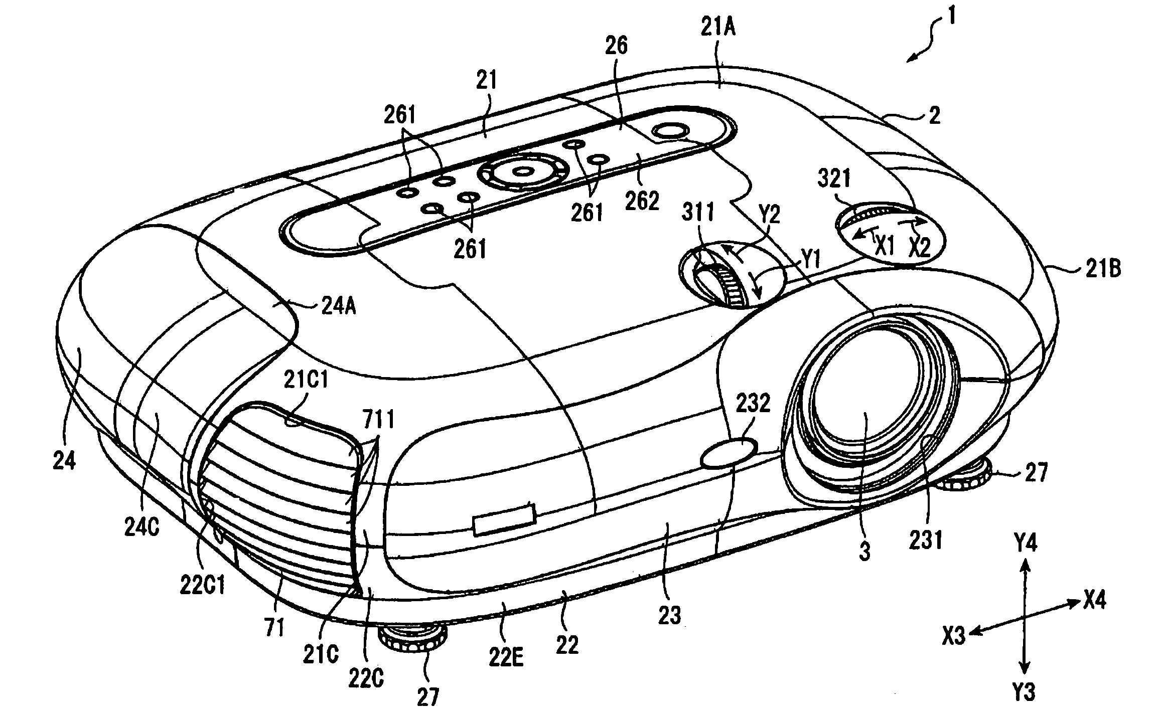
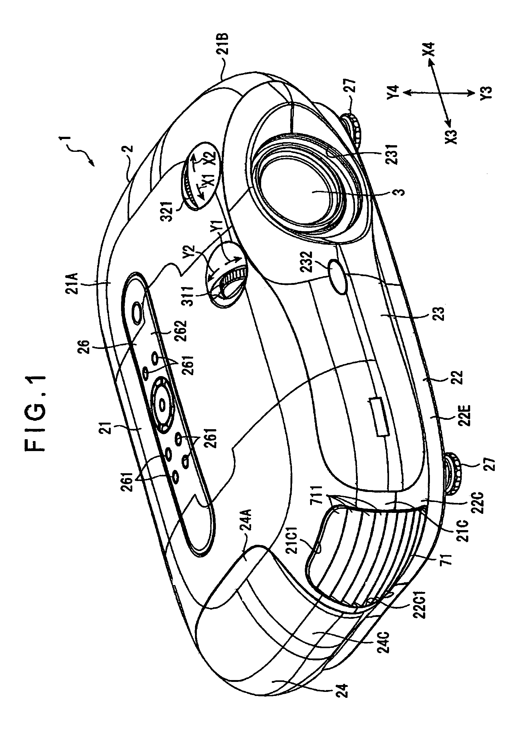
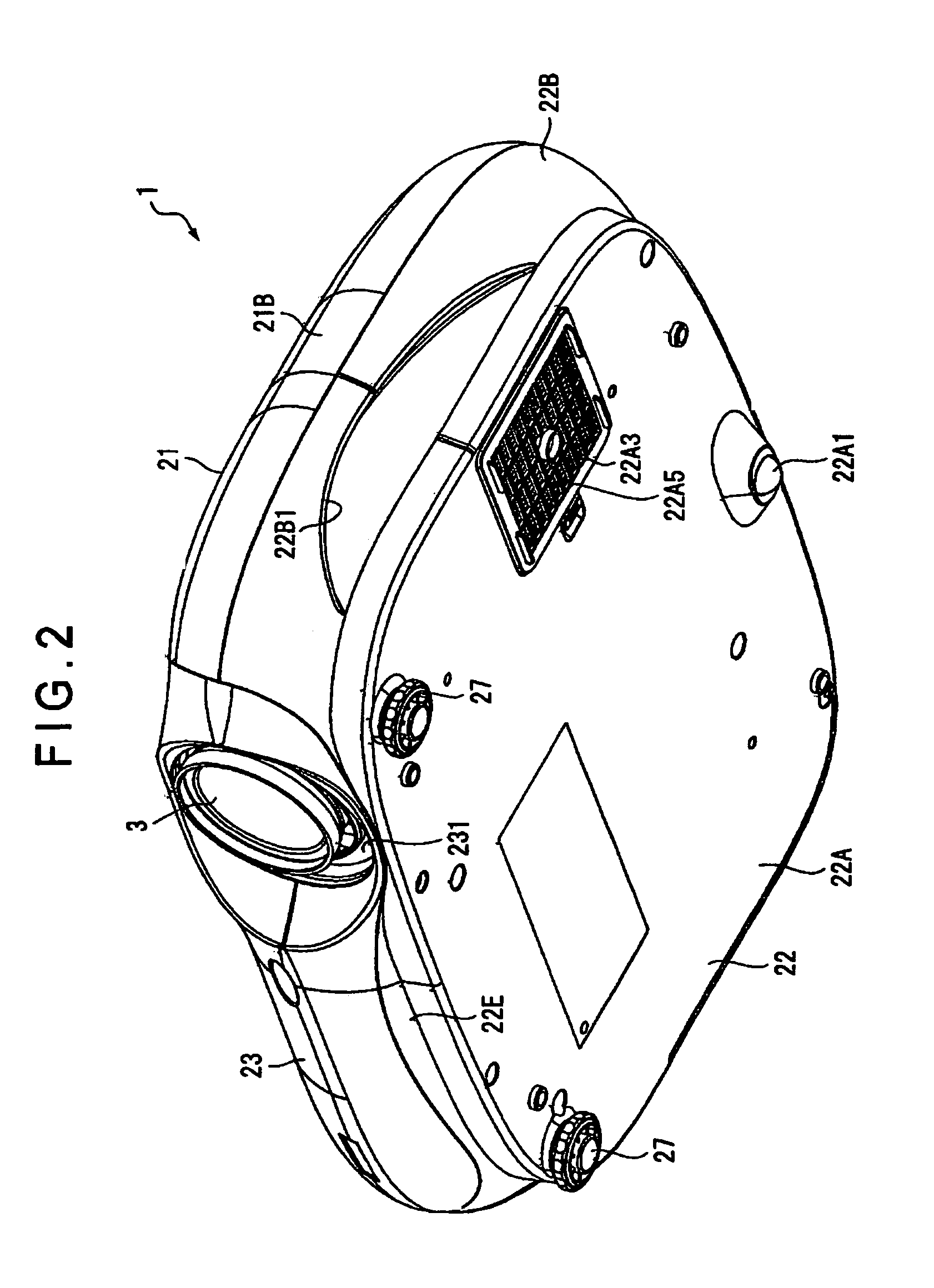
[0093]FIG. 1 is a schematic perspective view showing an upper front side of a projector 1 according to the present exemplary embodiment. FIG. 2 is a schematic perspective view showing a lower front side of the projector 1. FIG. 3 is a schematic perspective view showing an upper rear side of the projector 1. FIG. 4 is a schematic perspective view showing a part of an exterior case 2 of the projector 1.

[0094]The projector 1 modulates a light beam irradiated by a light source in accordance with image information and projects the light beam on a projection surface such as a screen in an enlarged manner. As shown in FIGS. 1 to 3, the projector 1 has an approximately rectangular parallelepiped exterior case 2 and a projection lens 3 exposed from the exterior case 2.

[0095]The projection lens 3 serves as a projection optical system that projects in an enlarged manner an optical image modulated by a liquid crystal panel, which is a below-described optical modulator. T...

second exemplary embodiment

[Second Exemplary Embodiment]

[0278]Next, a second exemplary embodiment of the present invention will be described below. Incidentally, in the following description, the same reference numeral will be attached to the same components as the above to omit the description thereof. Further, in this embodiment, components which are not particularly described herein may be configured in the same manner as the first exemplary embodiment.

[0279]In the above exemplary embodiment, the spring piece 37 abuts on the X-slider 324 while the protrusion 371 of the spring piece 37 engages with the recess 324C formed on the X-slider 324. In contrast, in the present exemplary embodiment, as shown in FIG. 17, the protrusion 371 engages with a recess 321F formed on a shaft 321C′ of a dial 321′. That is, in the present exemplary embodiment, the recognizer for recognizing the reference position is constituted of the spring piece 37 and the shaft 321C′ of the dial 321′.

[0280]The shaft 231C′ has a large-diamet...


PUM


Abstract

According to exemplary embodiments of the present invention, in a projection lens position adjuster, when a part of a dial exposed from an exterior case is rotated downward, a gear is rotated in an R2 direction. A Y-slider is then moved downward (in a Y3 direction). Accordingly, a Y-table is moved downward, as is a projection lens. When the part of the dial exposed from the exterior case is rotated upward, the projection lens is moved upward. When a part of a dial exposed form the exterior case is rotated leftward as seen from a rear side of a projector, the projection lens is moved leftward. In contrast, when the dial is rotated rightward, the projection lens is moved rightward. Provided around the projection lens are a first light shield for closing a gap between an opening of a front case and a periphery of the projection lens, and a second light shield for closing a gap between the projection lens and a hole of a base of the projection lens position adjuster. A shield body of the first light shield includes a ring-shaped elastic member disposed to extend between a ring and the projection lens, and a pair of attachments extending from the elastic member outward.

Description

BACKGROUND OF THE INVENTION[0001]1. Field of Invention[0002]The present invention relates to a projector.[0003]2. Description of Related Art[0004]The related art includes projectors that are used for presentations at conferences, academic societies and exhibitions. Each of such projectors modulates and combines a light beam irradiated by a light source in accordance with image information and projects the light beam on a screen by a projection optical system in an enlarged manner.[0005]In the above projector, there may be an occasion of projecting upward with the projector fixed at a lower level, or that of projecting downward with the projector fixed at a higher level. Related art document JP10-171044A, 3 to 4 pages, FIG. 2, discloses a projector, which is provided with a projection optical system position adjuster at an optical system such as an optical modulator etc. The projection optical system position adjuster moves a projection optical system in a direction orthogonal to a l...

Claims


Application Information

Patent Timeline
Patent Type & Authority Patents(United States)
IPC IPC(8): G03B21/14G03B5/04G03B21/00G03B21/26H04N5/74
CPCG03B21/14G03B5/04G03B3/02G03B5/02G03B21/142G03B21/147
Inventor KURODA, AKITOSHIMOMOSE, AKIRA
Owner SEIKO EPSON CORP
Why Eureka
Try Eureka