Tapping screw

a screw and screw body technology, applied in the direction of screws, threaded fasteners, fastening means, etc., can solve the problems of insufficient force of screw fixing with an object, high cost, and groove location

Inactive Publication Date: 2006-08-15
CHEN HO TIEN
View PDF7 Cites 20 Cited by
  • Summary
  • Abstract
  • Description
  • Claims
  • Application Information

AI Technical Summary

Benefits of technology

[0009]The invention has been devised to offer a tapping screw having function of smooth exhaust of cut wood waste and original cutting sharpness and strong force of fixing an object firmly.
[0011]1. An annular groove is provided between a shank and a cutting member so as to get rid of cut wood waste by cutting grooves smoothly out of the drilled hole.
[0012]2. The cutting member is made as shorter as could be than the conventional screws with a pointed end so as to smooth exhausting of cut wood waste.

Problems solved by technology

The cutting member 22 has a plurality of cutting grooves 220 vertically formed, and a plurality of wings 221, but the wings 221 are not parallel to the cutting grooves 220, so the cutting grooves 220 and the wings 221 needs a separate process, that is, two processes for forming, resulting in high cost.
The common disadvantage of the three kinds of conventional tapping screw mentioned above is that the cutting grooves are located in the lower end portion of a screw, regardless of the cutting grooves being long or short.
Then only a small portion instead of the whole portion of the male threads can engage with the hole 420, resulting in insufficient force of fixing of the screw with an object.

Method used


Image

  • Tapping screw
  • Tapping screw
  • Tapping screw

Examples


second embodiment

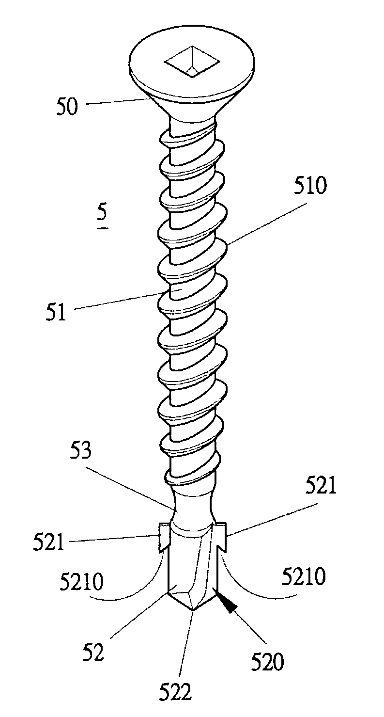
[0037]The cutting member 52 is provided with a plurality of cutting grooves 520 and a plurality of wings 521 located parallel to the cutting grooves 520 to enable the cutting member 52 formed by only one process. Or as shown in FIGS. 10 and 11, a tapping screw in the present invention has the cutting grooves 520 and the wings 521 formed in non-parallel to each other, which are then formed by two processes instead of one. Further, the wings 521 have an inclined surface 5210 formed in a lower side.

[0038]In addition, an annular groove 53 is provided between the shank 51 and the cutting member 52 for a large volume of cut wood waste 530 to easily and quickly move out of a drilled hole in fixing action of the screw. Then the screw 5 in the invention can force wood waste 600 coming from a drilled hole 60 of a wood board (or an object to be fixed) to move from the cutting groove 520 to the annular groove 53 and then exhausted out, as shown in FIG. 12. Therefore cut wood waste may not accum...

seventh embodiment

[0041]Next, FIGS. 18, 19 and 20 respectively show a fifth, a sixth and a screw in the invention, all including a head 50, a shank 51 with male threads 510 and a cutting member 52.

[0042]The cutting member 52 is provided with a plurality of cutting grooves 520, and an annular groove 53 is provided between the shank 51 and the cutting member 52 for a large volume of wood waste 530 to move in quickly. Therefore, in fixing a screw 5 in the invention, cut wood waste 600 from the drilled hole 60 may be moved from the cutting grooves 520 into the annular groove 53 to be exhausted out so cut wood waste may not remain in a large quantity in the cutting grooves to dull keen sharpness of the edges of the cutting member and the pointed end.

[0043]Further, the sixth embodiment shown in FIG. 19 can be formed to have the annular groove 53 with a wide upper portion and a narrow lower portion. Or the annular groove 53 can be formed as shown in FIG. 20 illustrating the seventh embodiment, having a narr...


PUM


Abstract

A tapping screw includes a head, a shank and a cutting member, Said the shank has male threads, and the cutting member extends down from the shank and has a plurality of cutting grooves lengthwise formed and / or a plurality of wings also lengthwise formed; an annular groove is further provided between the shank and the cutting groove for wood waste cut out of a drilled hole of an object to move out smoothly and quickly, so the sharpness of the cutting member and the pointed end may be kept usual, and resistance against drilling and fixing of the screw may be reduced.

Description

BACKGROUND OF THE INVENTION[0001]1. Field of the Invention[0002]This invention relates to a tapping screw, particularly to one possible to force cut wood waste move out of an object being fixed, and to shorten a cutting member as possible, and to elevate fixing force of a screw.[0003]2. Description of the Prior Art[0004]A first conventional tapping screw 1 shown in FIGS. 1 and 2, includes a head 10, a shank 11 provided with male threads 110, a cutting member 12 provided with a plurality of cutting grooves 120 and a plurality of wings 121 projecting outward from the outer surface of the cutting member 12. The wings 121 are formed in parallel vertically to the cutting grooves 120 so that the cutting member may be formed with one round of process. The wings 121 respectively have an inclined cut surface 1210 respectively formed at its lower side.[0005]A second conventional tapping screw 2 shown in FIG. 3 includes a head 20, a shank 21, and cutting member 22. The cutting member 22 has a ...

Claims


Application Information

Patent Timeline
Patent Type & Authority Patents(United States)
IPC IPC(8): F16B25/10
CPCF16B25/0031F16B25/103F16B25/0089
Inventor CHEN, HO-TIEN
Owner CHEN HO TIEN
Why Eureka
Try Eureka