Circuit breaker with improved arc extinction system

a circuit breaker and arc extinction technology, applied in the field of circuit breakers, can solve the problems of electrical arcs that have a tendency to vaporize materials, circuit breakers have not been without limitations, etc., and achieve the effects of reducing concentration, limiting arc movement, and promoting plasma deionization

Inactive Publication Date: 2006-08-15
EATON CORP
View PDF7 Cites 1 Cited by
  • Summary
  • Abstract
  • Description
  • Claims
  • Application Information

AI Technical Summary

Benefits of technology

[0007]An improved circuit breaker includes an arc extinction system having one or more insulators that generate a desirable gas in the presence of an arc. The exemplary circuit breaker includes gas-generating insulators disposed at three sides of a stationary contact and an arc chute at a fourth side of the stationary contact. The gas promotes the desirable extinction of the arc in a number of exemplary fashions. The presence of the gas on three sides of the stationary contact can resist movement of the arc toward the gas, thereby substantially limiting movement of the arc in a direction other than toward the arc chute. The gas can remove heat from the arc, thereby promoting deionization of the plasma by forming neutral molecular species at a lower temperature state. The presence of the gas can reduce the concentration of ions and electrons within the interior of the circuit breaker and can increase the pressure within the circuit breaker, and these also facilitate extinction of the arc.
[0011]Another aspect of the invention is to provide an improved circuit breaker having insulators that provide a gas in the presence of an arc to reduce the temperature of the arc.

Problems solved by technology

While such circuit breakers have been generally effective for their intended purposes, such circuit breakers have not, however, been without limitation.
Such electrical arcs have a tendency to vaporize material within the interior of the circuit breaker.

Method used


Image

  • Circuit breaker with improved arc extinction system
  • Circuit breaker with improved arc extinction system
  • Circuit breaker with improved arc extinction system

Examples


Embodiment Construction

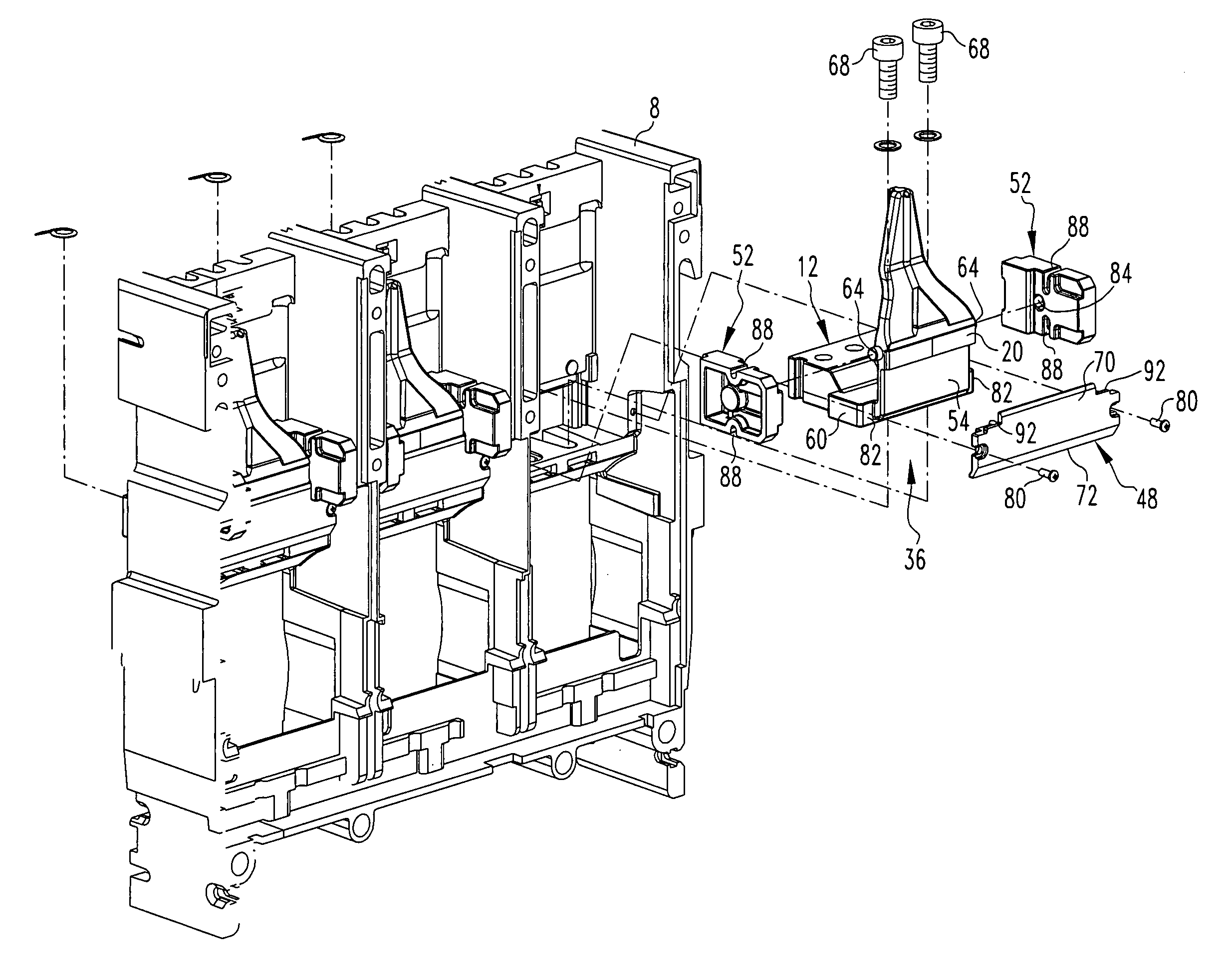
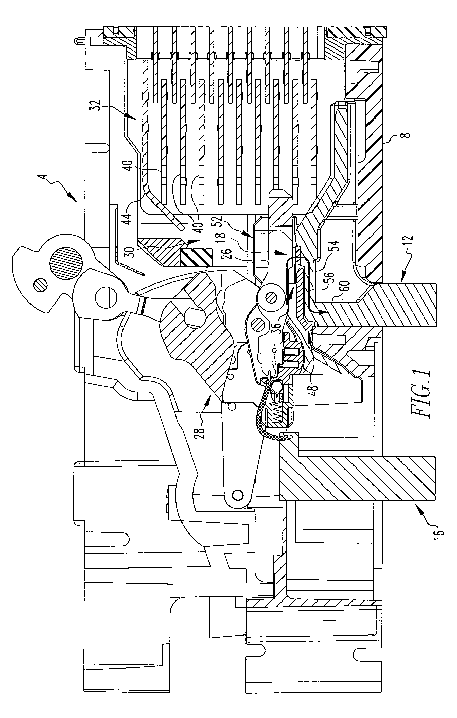
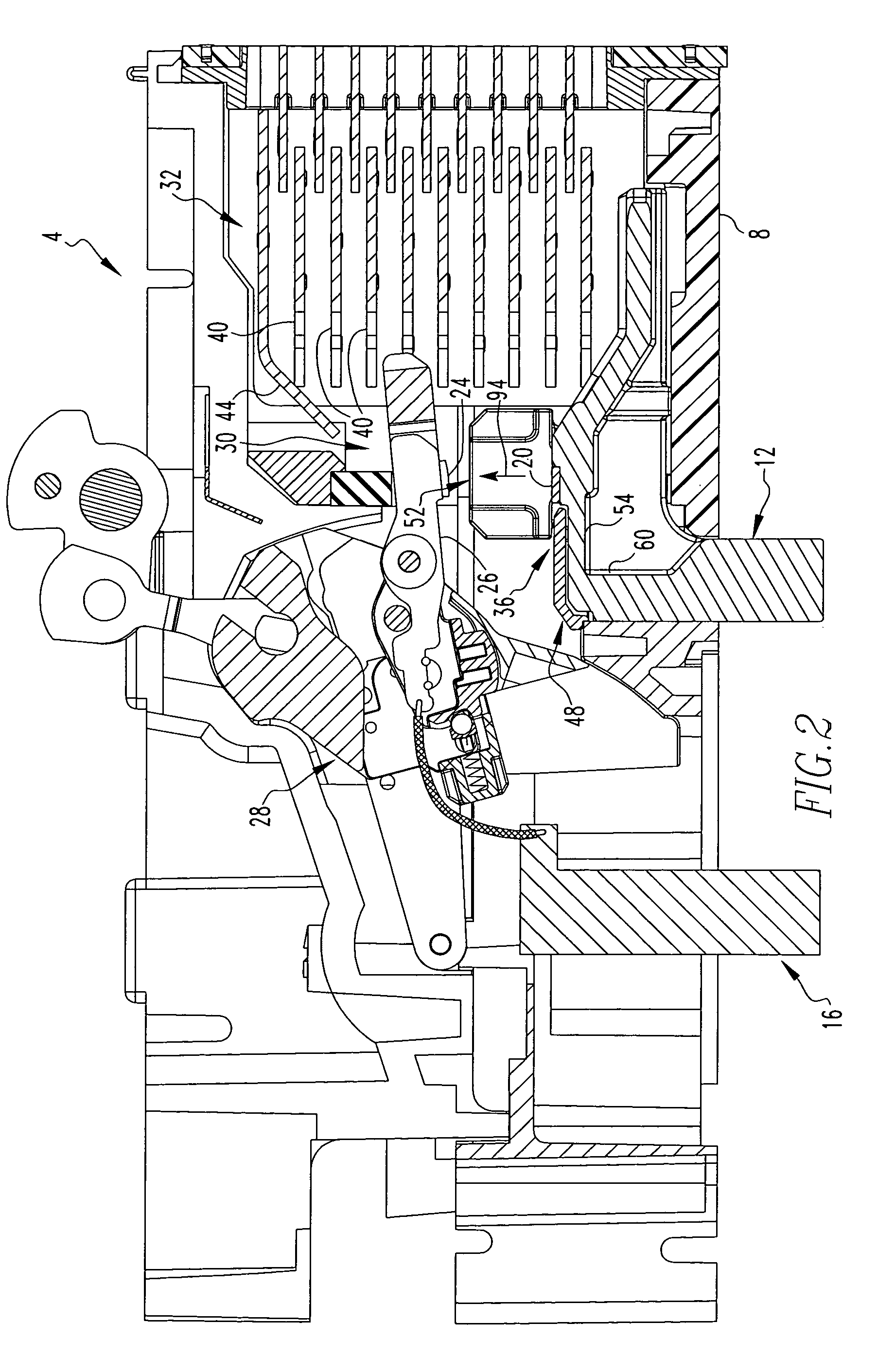
[0024]An improved circuit breaker 4 in accordance with the invention is indicated in a cut away fashion FIGS. 1–3. While FIGS. 1–3 depict a single pole of the circuit breaker 4, it is understood that the circuit breaker 4 may, for example, be a multi-pole circuit breaker that includes a plurality of the depicted poles connected together in an understood fashion.

[0025]The circuit breaker 4 can be generally stated as including a case 8, a line conductor 12, a load conductor 16, and a set of contacts 18. The set of contacts 18 includes a stationary contact 20 and a movable contact 24 that are separable from one another in one or more predetermined circumstances to open a circuit that includes the circuit breaker 4.

[0026]The movable contact 24 is disposed on a movable arm 26 of the load conductor 16, and the movable arm 26 is disposed on a moving contact assembly 28. Movement of the movable arm 26 causes the movable contact 24 to be separated from the stationary contact 20.

[0027]The cir...


PUM


Abstract

An improved circuit breaker includes an arc extinction system having one or more insulators that generates a desirable gas in the presence of an arc. The exemplary circuit breaker includes gas-generating insulators disposed at three sides of a stationary contact and an arc chute at a fourth side of the stationary contact. The gas promotes the desirable extinction of the arc in a number of exemplary fashions. The presence of the gas on three sides of the stationary contact can resist movement of the arc toward the gas, thereby substantially limiting movement of the arc in a direction other than toward the arc chute. The gas can remove heat from the arc, thereby promoting deionization of the plasma by forming neutral molecular species at a lower temperature state. The presence of the gas can reduce the concentration of ions and electrons within the interior of the circuit breaker and can increase the pressure within the circuit breaker, and these also facilitate extinction of the arc.

Description

BACKGROUND OF THE INVENTION[0001]1. Field of the Invention[0002]The invention relates generally to circuit breakers and, more particularly, to a circuit breaker having an improved arc extinction system that provides a gas in the presence of an arc.[0003]2. Description of the Related Art[0004]Circuit breakers are generally well known and are used in numerous applications. Circuit breakers can be used to interrupt a circuit under certain predetermined circumstances, and can be used for other purposes.[0005]A typical circuit breaker might include a set of separable contacts that can be separated in certain predetermined circumstances to open a circuit. The separable contacts might include one or more movable contacts that are disposed on a movable arm which, when moved, can separate the one or more movable contacts from one or more stationary contacts to interrupt the circuit. As the movable contacts begin to move away from the stationary contacts, an electrical arc oftentimes forms be...

Claims


Application Information

Patent Timeline
Patent Type & Authority Patents(United States)
IPC IPC(8): H01H33/02
CPCH01H9/346H01H9/302
Inventor SHEA, JOHN JOSEPHRAKUS, PAUL RICHARDPENDRICK, THOMAS CLEMENTS
Owner EATON CORP
Why Eureka
Try Eureka