Limiting circuit with level limited feedback

a feedback circuit and feedback technology, applied in the field of data communication, can solve the problems of reducing the sensitivity of the receiver, limiting the amount of data and/or the distance over which data can be transmitted, and introducing distortion in the feedback stag

Active Publication Date: 2006-08-15
XILINX INC
View PDF3 Cites 6 Cited by
  • Summary
  • Abstract
  • Description
  • Claims
  • Application Information

AI Technical Summary

Problems solved by technology

However, as signal magnitude increases, the feedback stage introduces distortion, in the form of jitter, due to severe reverse biasing of the gate-source volta...

Method used


Image

  • Limiting circuit with level limited feedback
  • Limiting circuit with level limited feedback
  • Limiting circuit with level limited feedback

Examples


Embodiment Construction

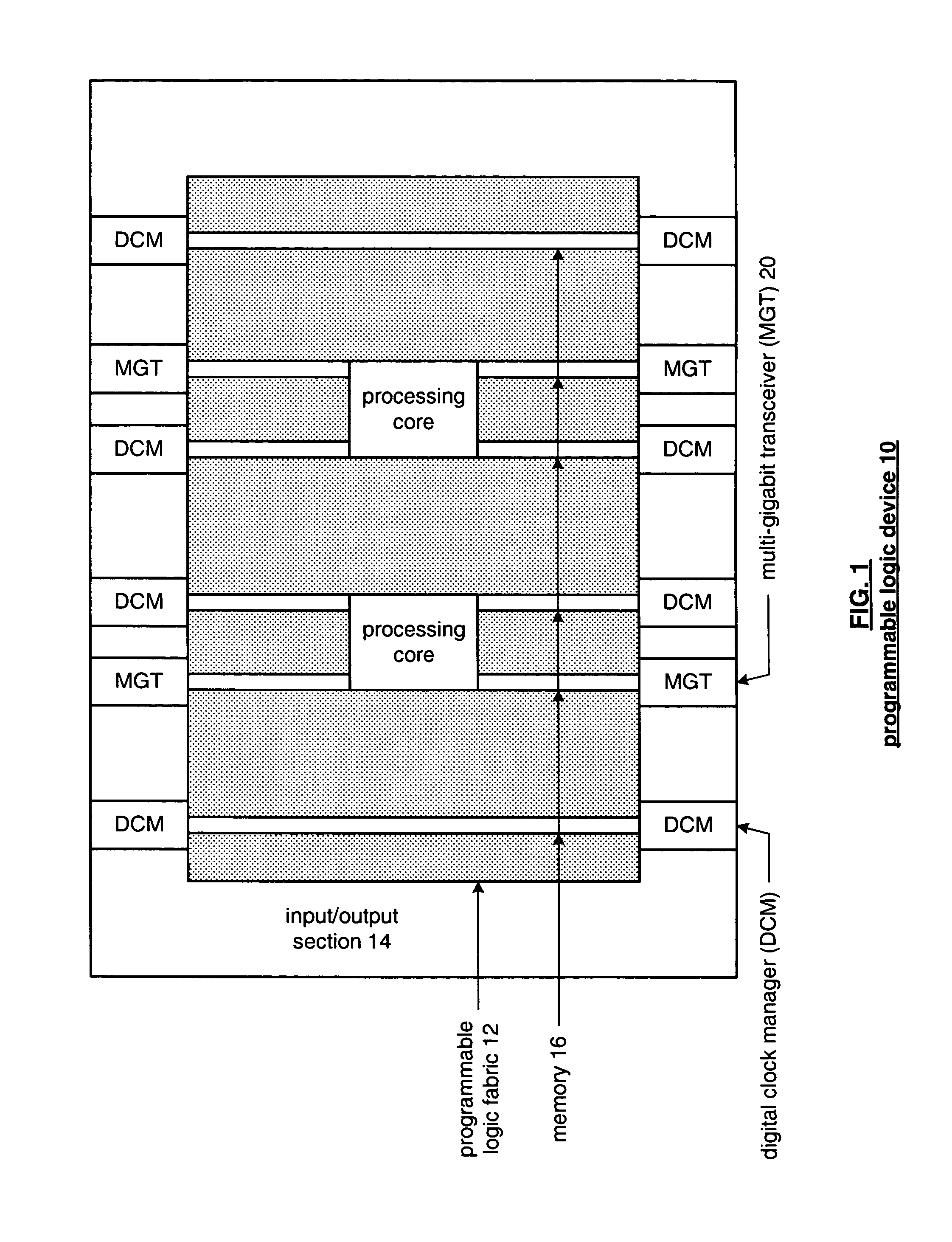
[0021]FIG. 1 is a schematic block diagram of a programmable logic device 10 that includes programmable logic fabric 12, an input / output section 14, and memory 16. The programmable logic fabric 12 may include one or more processing cores and programmable logic circuitry. Such programmable logic circuitry may include programmable logic arrays (PLAs), programmable array logic (PAL) devices, erasable programmable logic devices (EPLDs) and / or programmable gate arrays (PGAs). Memory 16 may be block random access memory (BRAM). Input / output section 14 may include a plurality of digital clock managers (DCMs) and a plurality of multi-gigabit transceivers (MGTs). Other programmable logic device embodiments may include other configurable resources in other configurations. An example of an alternate embodiment is described in U.S. patent application Ser. No. 10 / 683,944, entitled “Columnar Architecture” by Young, filed on Oct. 10, 2003, and incorporated herein in its entirety.

[0022]The digital c...


PUM


Abstract

A limiting circuit includes an input transconductance stage, an output transconductance stage, a feedback transconductance stage, first and second resistive loads, and a level limiting circuit. The input transconductance stage is operably coupled to convert an input voltage signal into an input current signal. The first resistive load is operably coupled to convert the input current signal and a feedback current signal into an intermediate output voltage signal. The output transconductance stage is operably coupled to convert the intermediate output voltage signal into an output current signal. The second resistive load is operably coupled to convert the output current signal into an output voltage signal. The feedback transconductance stage is operably coupled to produce the feedback current signal based on the output voltage signal. The level limiting module is operably coupled to limit at least one voltage level of the feedback transconductance stage.

Description

BACKGROUND OF THE INVENTION[0001]1. Technical Field of the Invention[0002]This invention relates generally to data communications and more particularly to limiting circuits within receivers of such data communications.[0003]2. Description of Related Art[0004]Communication systems are known to transport large amounts of data between a plurality of end user devices, which, for example, include telephones, facsimile machines, computers, television sets, cellular telephones, personal digital assistants, etc. As is also known, such communication systems may be local area networks (LANs) and / or wide area networks (WANs) that are stand-alone communication systems or interconnected to other LANs and / or WANs as part of a public switched telephone network (PSTN), packet switched data network (PSDN), integrated service digital network (ISDN), the Internet, etc. As is further known, communication systems include a plurality of system equipment to facilitate the transporting of data. Such system...

Claims


Application Information

Patent Timeline
IPC IPC(8): H03F1/36
CPCH03F1/34H03F3/45183H03F3/45475H03G11/02H03G11/008H03F2203/45652H03F2203/45472
Inventor BRUNN, BRIAN T.NIX, MICHAEL A.
Owner XILINX INC
Why Eureka
Try Eureka