Image reading apparatus and image input/output system

a reading apparatus and image technology, applied in the field of image reading apparatus and image input/output system, can solve the problems of shortening the load accumulation time of each image sensing, slowing the image sensing speed, and reducing the time required for image input and outpu

Inactive Publication Date: 2006-08-15
MINOLTA CO LTD
View PDF13 Cites 14 Cited by
  • Summary
  • Abstract
  • Description
  • Claims
  • Application Information

AI Technical Summary

Benefits of technology

[0011]An object of the present invention is to eliminate the aforesaid problems of the conventional examples. A further object of the present invention is to provide an image input device capable of scanning in optional directions to match the main scan direction of an output device while controlling energy consumption. A still further object of the present invention is to provide an image input / output system capable of reducing the time required for image input and output.

Problems solved by technology

However, the former method lengthens time required for image sensing of a single document, thus slowing the image sensing speed, On the other hand, the latter method shortens the load accumulation time of each image sensing and reduces S / N due to the small load accumulated by each photoelectric conversion element.
Although it is possible to increase S / N by increasing the brightness of the illumination device, a disadvantage arises in that energy consumption also increases.
Furthermore, since a large drive device is required due to rotate the heavy drum at high speed, another disadvantage arises in that a great deal of energy is consumed.
However, in the case of a drum scanner, the time required to sense one image is lengthened, and the image sensing speed is slowed, similar to the case of a drum scanner.
Although it is possible to increase the S / N by increasing the brightness of the illumination device, a disadvantage arises in that energy consumption also increases.
Furthermore, since a large drive device is required due to rotate the heavy drum at high speed, another disadvantage arises in that a great deal of energy is consumed.
Since the main scan direction of the scanner and the main scan direction of the output device may not match, disadvantages arise inasmuch as the transmission efficiency of the obtained image data is lowered, and high speed processing is not possible.

Method used


Image

  • Image reading apparatus and image input/output system
  • Image reading apparatus and image input/output system
  • Image reading apparatus and image input/output system

Examples


Embodiment Construction

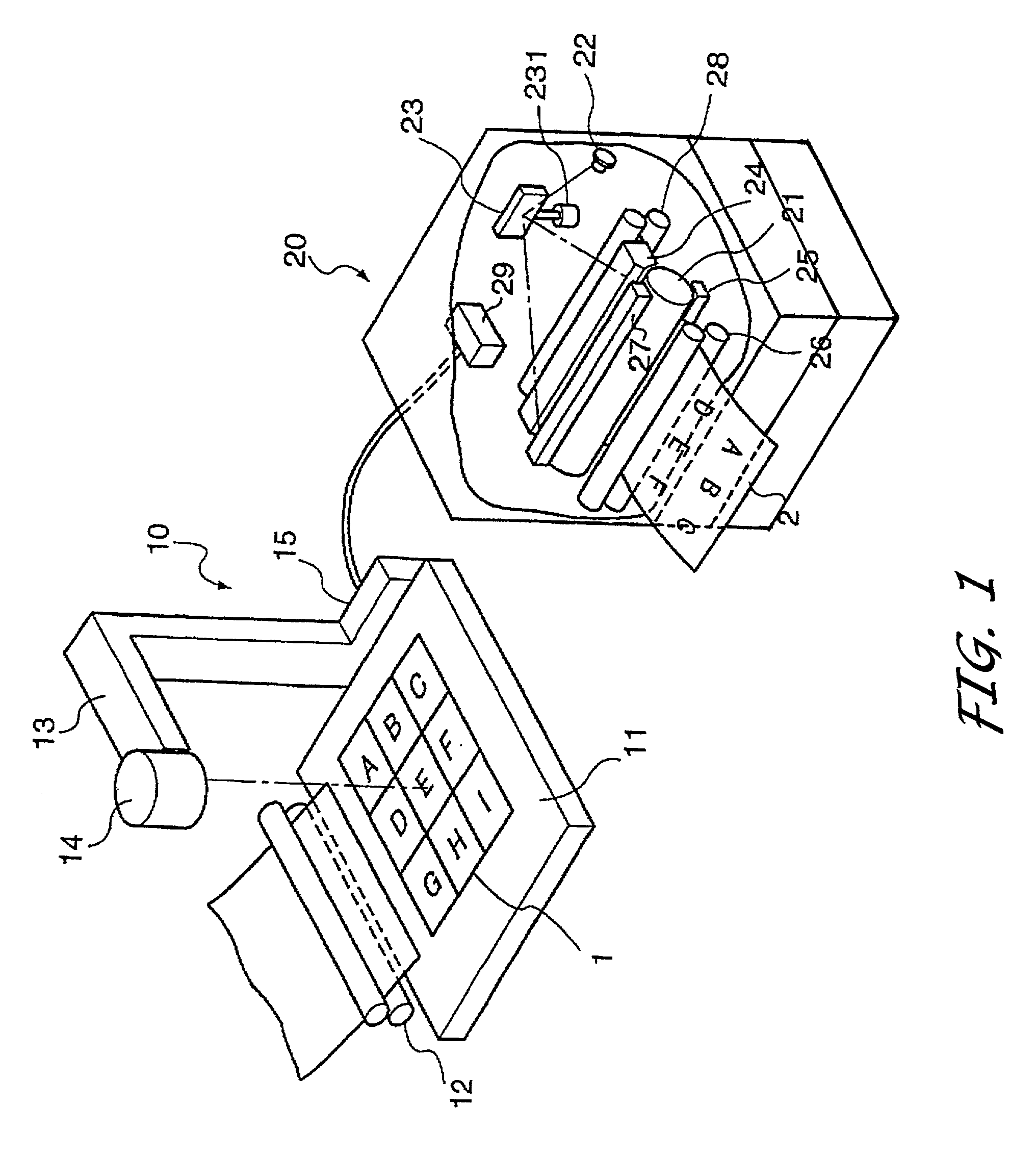
[0038]The embodiments of the present invention are described hereinafter with reference to the accompanying drawings. FIG. 1 shows an image input / output system connected to a laser printer as an image output device of the image input device of the present invention.

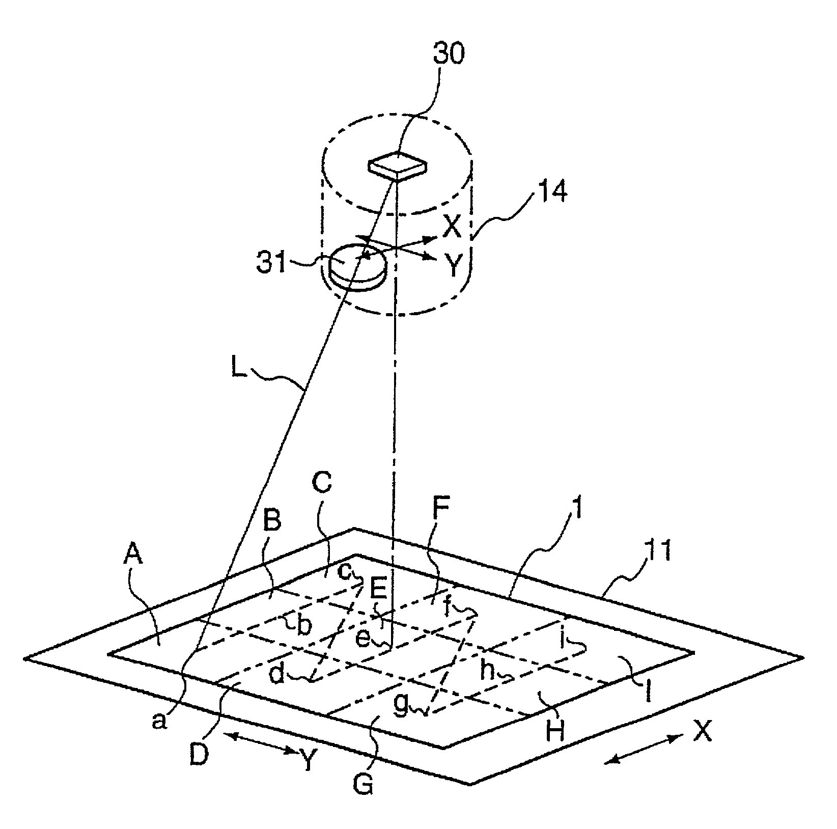
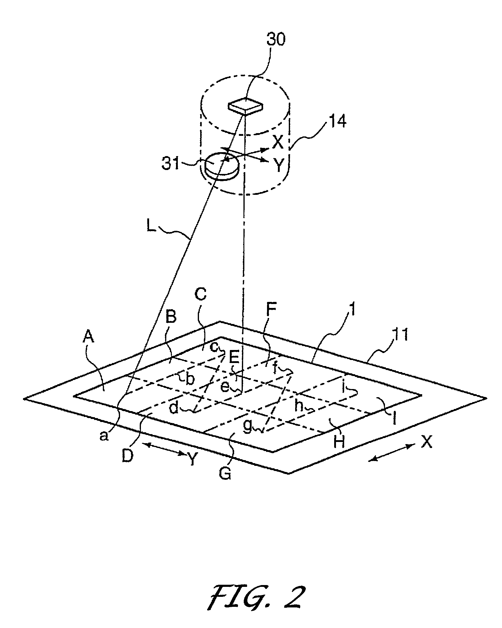
[0039]An image input device 10 comprises a table 11 for supporting a document 1 as a reading object, document feeder 12 for feeding a document onto the table 11, a column 13 rising upward perpendicularly from the table and bent toward the center of the table so as to be approximately horizontal, image sensing unit 14 provided on the end of the column 13 facing toward the center area of the table 11, and a control unit 15 provided with an internal control circuit.

[0040]The image input device 10 is provided with a document size sensor 107 for detecting the size of a document placed on the document table 11, and a operation panel 108 for receiving input such as paper cassette designation, magnification designation and the li...


PUM


Abstract

The purpose of obtaining a high resolution image with fewer number of image sensings in an image input device which allocates a planar object such as a document or the like into a plurality of areas for image sensing, and combines the obtained image data for output to a printer or display device or the like.
An image reading device using an area sensor as an image sensing element 30 which is stationary in an image sensing unit 14 facing the center of a document 1 on a table 11, and a taking lens 31 moves parallel to the document 1 and the image sensing element 30 to read the images of allocated sections A˜I of the document 1.

Description

RELATED APPLICATION[0001]This application is based on Patent Application No. 2000-029042 filed in Japan, the entire content of which is hereby incorporated by reference.BACKGROUND OF THE INVENTION[0002]1. Field of the Invention[0003]The present invention relates to an image input device for two-dimensionally scanning a planar object (hereinafter referred to as the “document”) such as, for example, a document, photograph and the like, and reading the image data thereby, and an image input / output system using the image input device.[0004]2. Description of the Related Art[0005]Drum type scanners and flatbed type scanners are known as conventional image input devices (scanners) capable of reading the image data of documents at high resolution.[0006]In the case of drum scanners, a document is adhered to the inside of a transparent hollow drum formed, for example, of glass or the like, and the drum is rotated about a center axis at constant speed (main scan). Furthermore, a point sensor i...

Claims


Application Information

Patent Timeline
Patent Type & Authority Patents(United States)
IPC IPC(8): H04N1/04H04N1/387G06T1/00H04N1/10H04N1/107H04N1/195
CPCH04N1/195H04N1/19589H04N1/3876H04N2201/0436H04N2201/0426
Inventor MATSUDA, SHINYA
Owner MINOLTA CO LTD
Why Eureka
Try Eureka