
Sound output apparatus for an automotive vehicle

a technology for automotive vehicles and output devices, which is applied in the direction of stereophonic arrangments, transportation and packaging, vehicle arrangements, etc., can solve the problems of driver or passenger not knowing the direction, driver or passenger's, and passenger's inability to understand contents or meanings

Inactive Publication Date: 2006-08-15
DENSO CORP
View PDF22 Cites 42 Cited by
  • Summary
  • Abstract
  • Description
  • Claims
  • Application Information

AI Technical Summary

Benefits of technology

[0010]In view of the above-described problems of the prior art, the present invention has an object to provide a sound output apparatus for an automotive vehicle which generates a virtual sound source in a passenger compartment based on a stereo dipole system and is capable of obtaining clear acoustic or sound image localization even when used loudspeakers are small or compact.
[0011]Another object of the present invention is to provide a sound output apparatus for an automotive vehicle which is capable of obtaining clear acoustic or sound image localization covering all of the angular regions including the back side of a driver or a passenger.

Problems solved by technology

However, even if warning sounds or alarms are generated, there will be the possibility that a driver or passenger cannot understand the contents or meaning of the immediately generating warning sounds or alarms and also cannot know the direction to which the driver's or passenger's caution should be directed.
However, if the warning sounds or alarms notifying the approach of any obstacle are always the same, a driver or passengers will not be able to immediately know or perceive the direction from which the detected obstacle is approaching.
The driver and passengers will not be able to promptly and properly respond to avoid the coming danger or increasing abnormality.
Therefore, it is difficult to obtain clear acoustic or sound image localization by using a car navigation system even if the stereo dipole system is employed.
If the loudspeakers are downsized in the future, the above distance L may be too long to obtain clear acoustic or sound image localization.
For example, according to the warning apparatus disclosed in the above-described prior art reference, a driver cannot obtain clear acoustic or sound image localization in an insensible region spreading at the back side of the driver when the loudspeakers of a car navigation system are positioned in front on a driver's seat.

Method used


Image

  • Sound output apparatus for an automotive vehicle
  • Sound output apparatus for an automotive vehicle
  • Sound output apparatus for an automotive vehicle

Examples


first embodiment

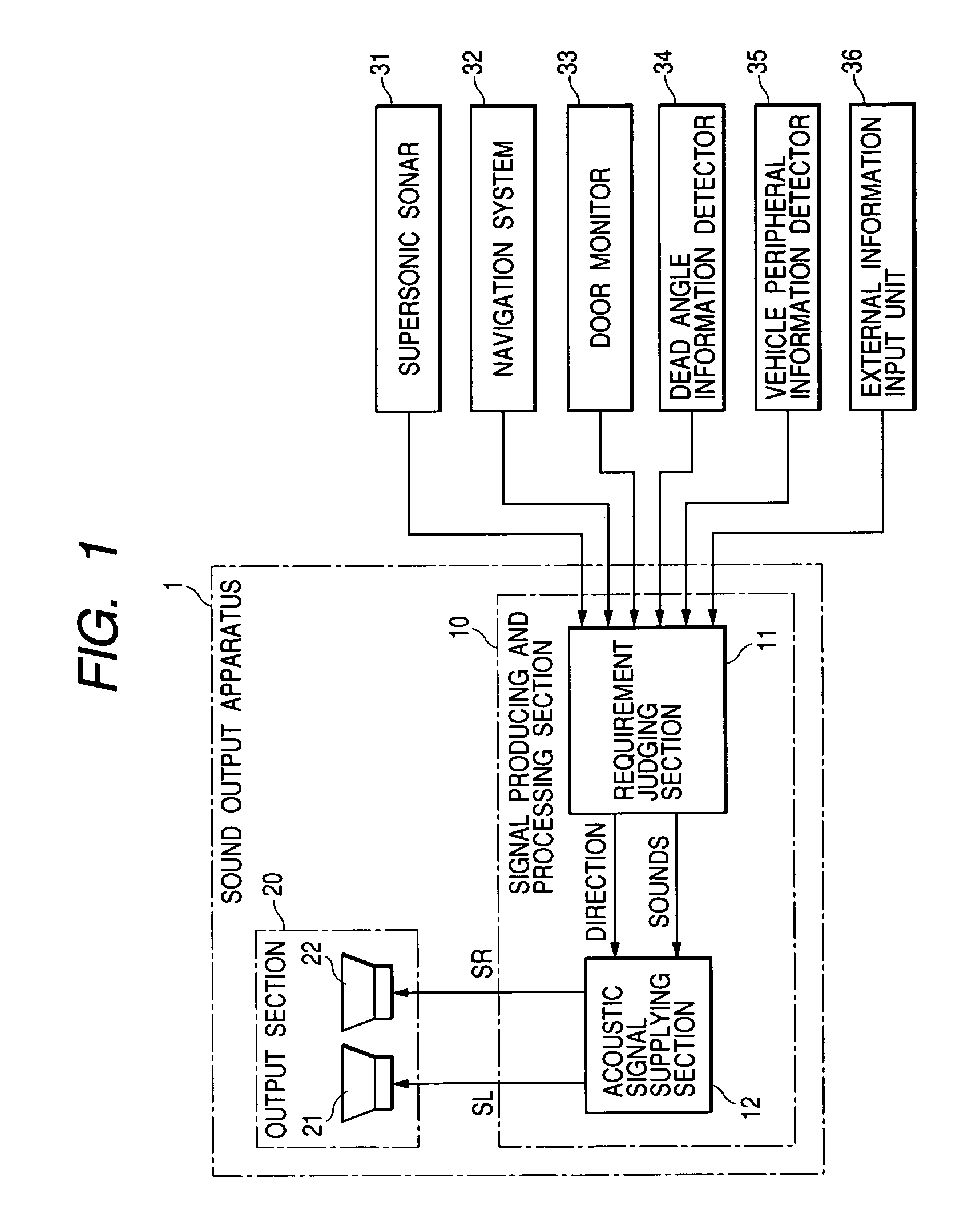
[0059]FIG. 1 shows an automotive acoustic system in accordance with a first embodiment of the present invention;

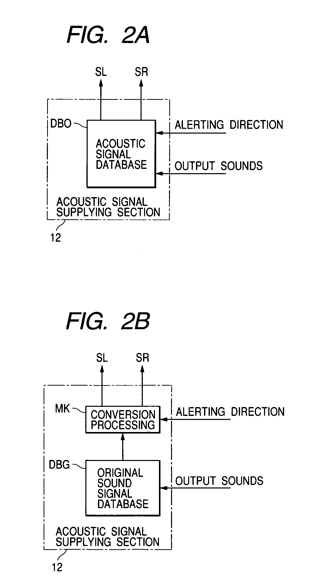
[0060]As shown in FIG. 1, a sound output apparatus 1 of the first embodiment includes a signal producing and processing section 10 and an output section 20. The signal producing and processing section 10, serving as acoustic signal producing means of the present invention, receives sound output requirements, i.e., requirements of generating warning sounds, alarms, or guide voice or speech, from various portions of a vehicle and produces a right channel signal SR and a left channel signal SL as acoustic signals for generating output sounds in accordance with the received sound output requirements. The output section 20 consists of a pair of loudspeakers 21 and 22, cooperatively serving as output sound generating means of the present invention, which reproduces a sound source of a stereo dipole type (i.e., generates output sounds).

[0061]The output section 20, consisting of t...

second embodiment

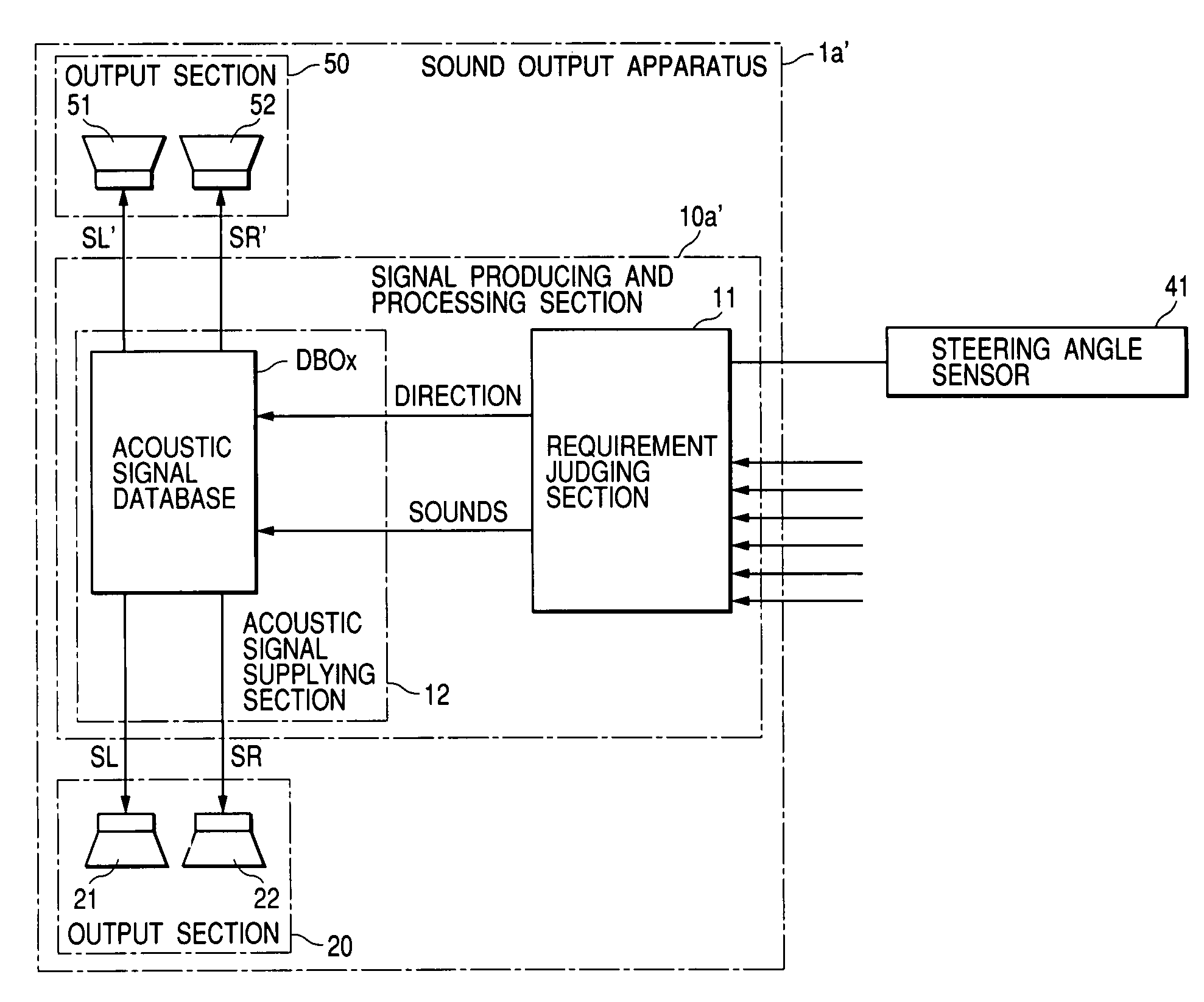
[0080]FIG. 5A shows an automotive acoustic system using a sound output apparatus 1a in accordance with a second embodiment of the present invention.

[0081]The sound output apparatus 1a of the second embodiment is different from the sound output apparatus 1 of the first embodiment in that the following components being newly added.

[0082]The sound output apparatus 1a consists of a signal producing and processing section 10a, the output section 20, and another output section 50. The output section 20, serving as a primary output section, includes a pair of loudspeakers 21 and 22 which is installed inside the seatback SB as already explained in the first embodiment. The output section 50, consisting of a pair of loudspeakers 51 and 52, is installed on a steering wheel ST.

[0083]For example, the output section 50 is installed at an upper portion of the steering wheel ST (when it is held at a neutral position) with respect to its rotary shaft as shown in FIG. 6A, or at a lower portion of th...

third embodiment

[0090]FIG. 8A shows a sound output apparatus 1b in accordance with a third embodiment which is different from the sound output apparatus 1 of the first embodiment or the sound output apparatus 1a of the second embodiment in the following features.

[0091]As shown in FIG. 8A, the sound output apparatus 1b consists of a signal producing and processing section 10b and an output section 20b. The signal producing and processing section 10b is different from the signal producing and processing section 10 of the first embodiment or the signal producing and processing section 10b of the second embodiment in that a transmitting section 15 is additionally provided. The transmitting section 15 receives the acoustic signals SR and SL supplied from the acoustic signal supplying section 12 or the correction processing section 14 and converts the received acoustic signals SR and SL into radio signals, and transmits the converted radio signals in the air. The output section 20b is different from the ...


PUM


Abstract

An output section, consisting of a pair of loudspeakers disposed adjacently to each other, is installed inside a seatback of a designated seat. Sound output surfaces of respective loudspeakers face a designated person sitting on the designated seat. It is hence easy to secure a required distance for obtaining clear acoustic image localization in accordance with the size of loudspeakers cooperatively constituting the output section.

Description

BACKGROUND OF THE INVENTION[0001]This invention relates to a sound output apparatus for an automotive vehicle which generates various acoustic or sound outputs, such as warning sounds, alarms, guide voice or speech, and others.[0002]Conventionally, an automotive vehicle is equipped with an acoustic or sound device for generating various acoustic or sound outputs to transmit necessary information to a driver or passengers in a passenger compartment. For example, various sensors are installed on an automotive vehicle to detect dangerous or abnormal conditions of the vehicle. When these sensors detect any dangerous or abnormal conditions of the vehicle, warning sounds, alarms, and voice or speech guidance from a navigation system will be generated to evoke driver's or passenger's caution and to let the driver or passengers act or behave appropriately to avoid the encountering danger or abnormality.[0003]However, even if warning sounds or alarms are generated, there will be the possibil...

Claims


Application Information

Patent Timeline
Patent Type & Authority Patents(United States)
IPC IPC(8): H04B1/00B60Q1/00H03G5/00H04B5/00H04R29/00H04R5/00B60R16/02B60N2/90B60R11/00B60R11/02H04R1/40H04R3/12H04S1/00
CPCB60R11/0217H04R1/403H04R3/12B60R2011/0005B60R2011/001B60R2011/0012H04R2499/13B60R2011/0017B60R2011/0028B60R2011/0015
Inventor ENYA, TAKESHISATO, YOSHIHISAAICHI, ISAO
Owner DENSO CORP
Learn More